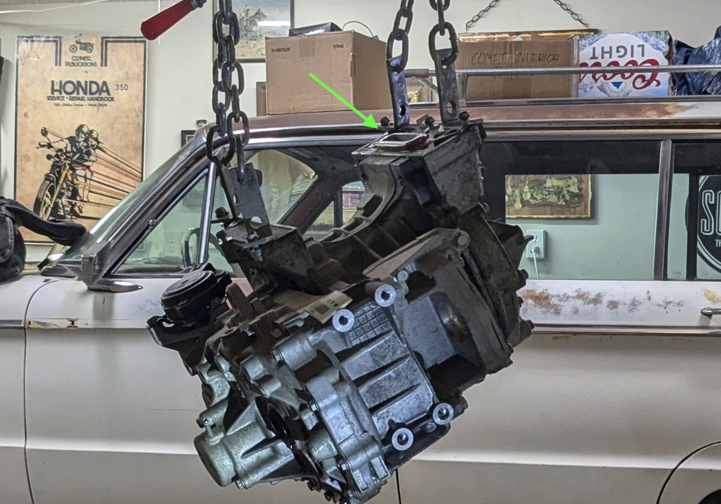
In previous chapters for Project E.V.Oh Speedwagon, I divorced the motor and invert. From the Nissan factory (in Tennessee) the inverter came stacked on top of the motor, and three bus bars protruded down and into the motor where they could be fastened down to make the high-voltage connections. But now that they're separated, I'll need to make new connections via a length of HV cable.
I'll start with the motor. Here it is with the inverter removed, the green arrow shows where the inverter's bus wars would go. Now it is a big hole that needs to be filled.
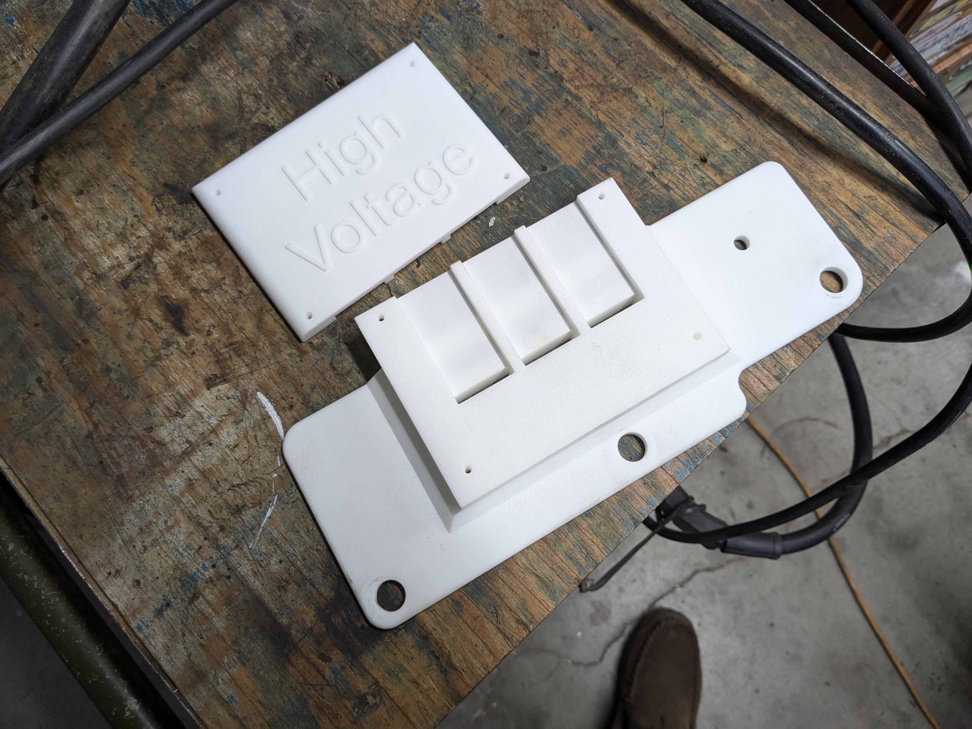
Thankfully for me, another EV builder created a 3d-printed cover to both seal this hole and isolate the bus bars that will need to be used. He shared the file to makerworld.com and I downloaded it and sent it to Shapeways.com. They printed it for me and mailed it to me for about $150. The material I chose was nylon, which has a high melting point and is a great insulator.
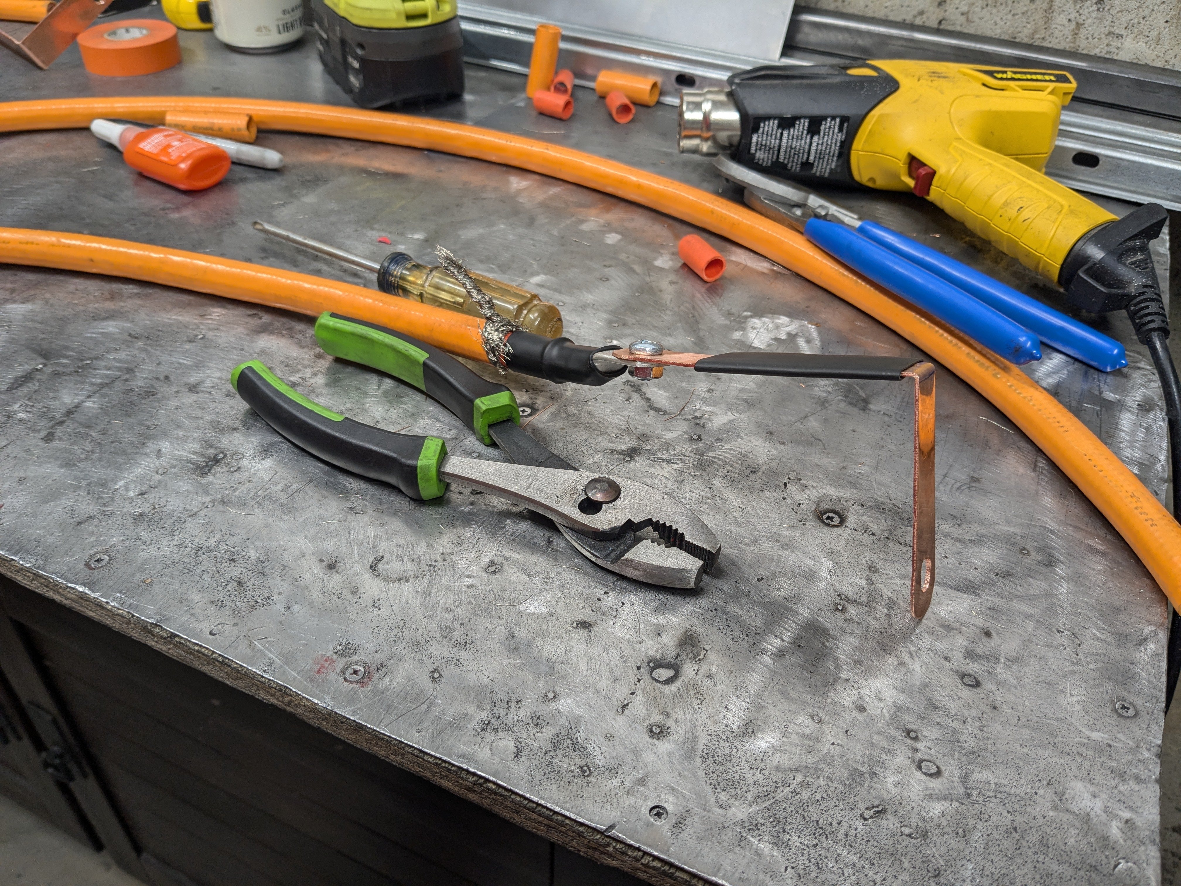
Here's the rest of the stuff I'll need to build HV connections between the motor and inverter. All in all I spent around $400 on all of it! Insane.
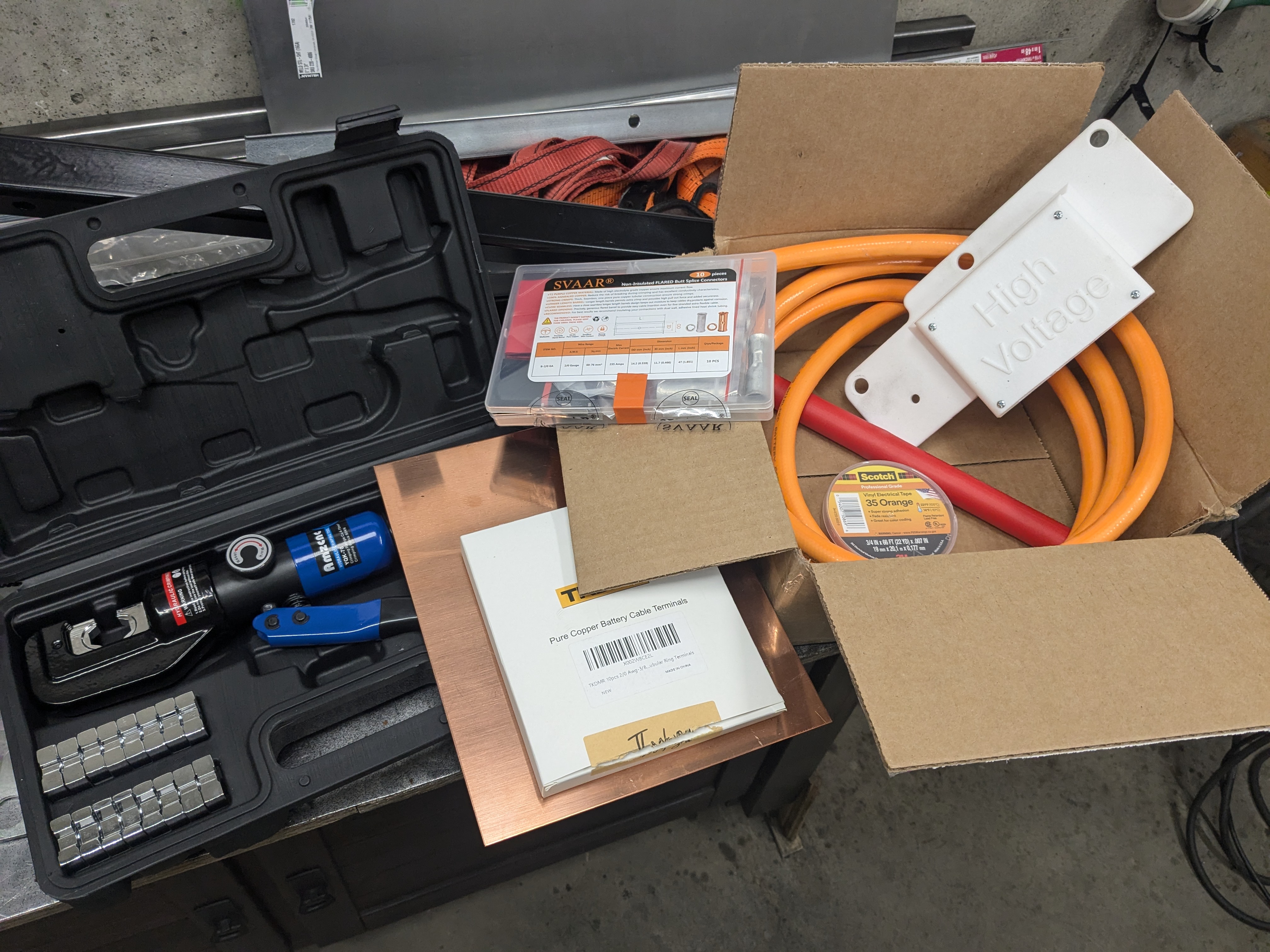
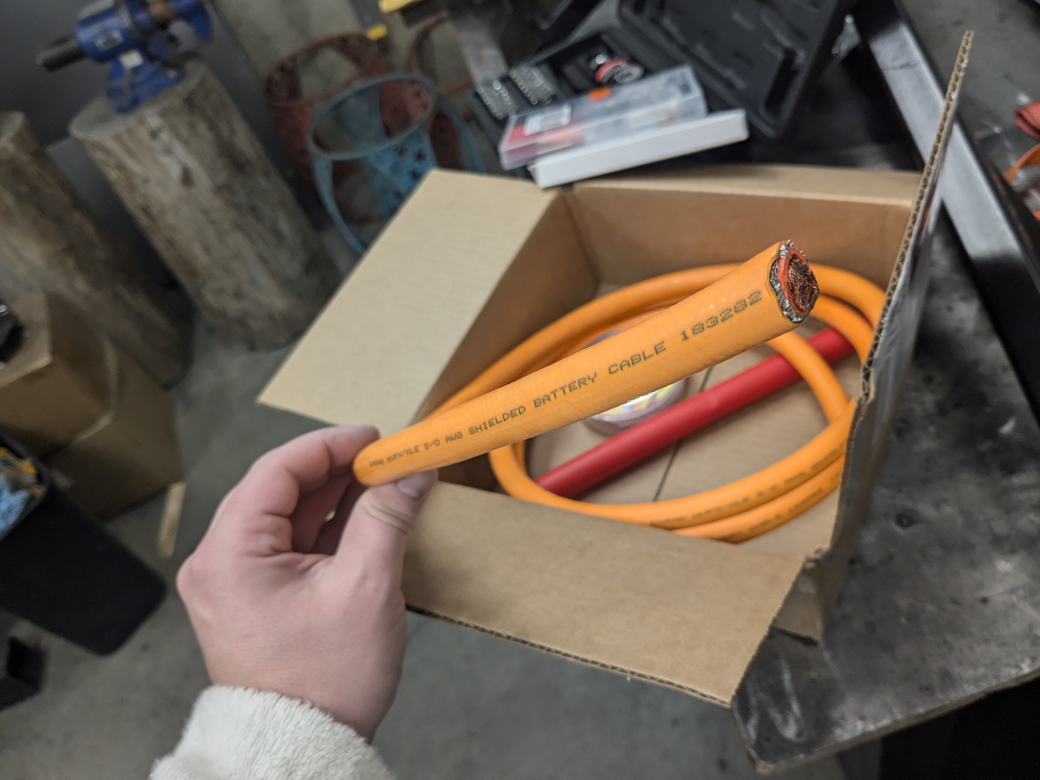
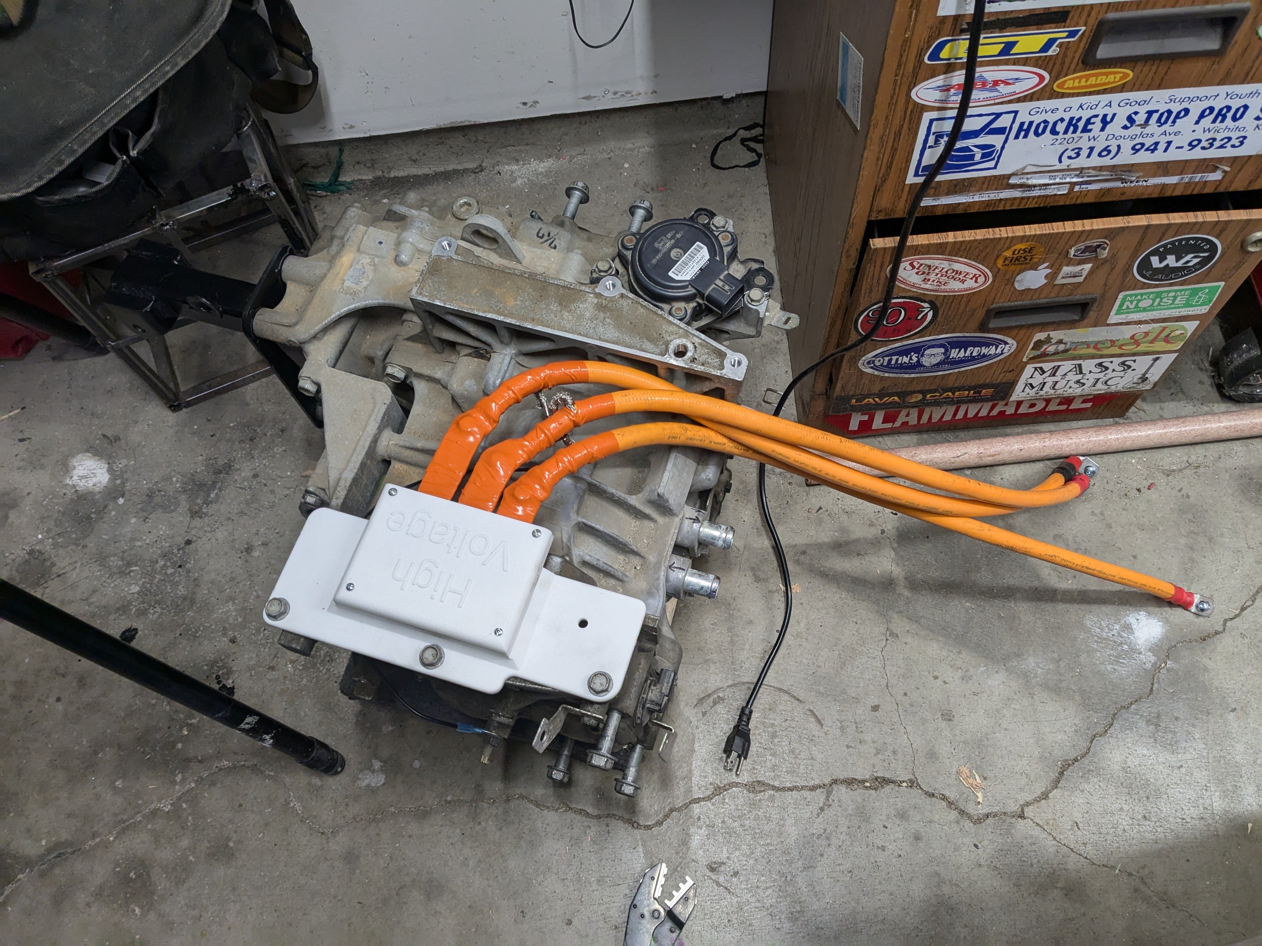
I used 2/0 shielded HV cable from EV West. 2/0 is bigger than I needed and I could have used 1/0 but this way I could upgrade the inverter and not have to redo the wiring. The Gen 2 Leaf inverters put out 110kW and 148hp, I have the 1st Gen inverter for now.
I clamped on copper bus bars (nickle plated) using a hydraulic crimper too.
Next, I built three bus bars out of copper. They're 7/8" wide and, honestly I can't remember how thick they are. 16awg? I just used hand tools to cut and shape them.
The bus bars where then test fitted before fastening them to the cables. I used 1/4" hardware with just a little dab of threadlocker so that they can't come loose but also it wouldn't ooze out and get between the the lugs and the bus bars and add resistance to the electrical connection.
Here it is all ready to go back under the car. You can see I made the bus bars at slightly different lengths to help package it all a little bit better. I also cut the cables to be slightly different lengths so that the overall lengths were all exactly the same. Just in case different lengths would cause and problems, electrically.
I could have saved almost $200 by not using the 3d-printed cover and bus bars. Instead, I could have put the HV cables into the opening in the top of the motor and then sealed it with a large amount of silicone. But I didn't have enough the clearance above the motor, and the shielded wire is very hard to bend to a 90 degree angle. Plus that would have been an ugly mess.
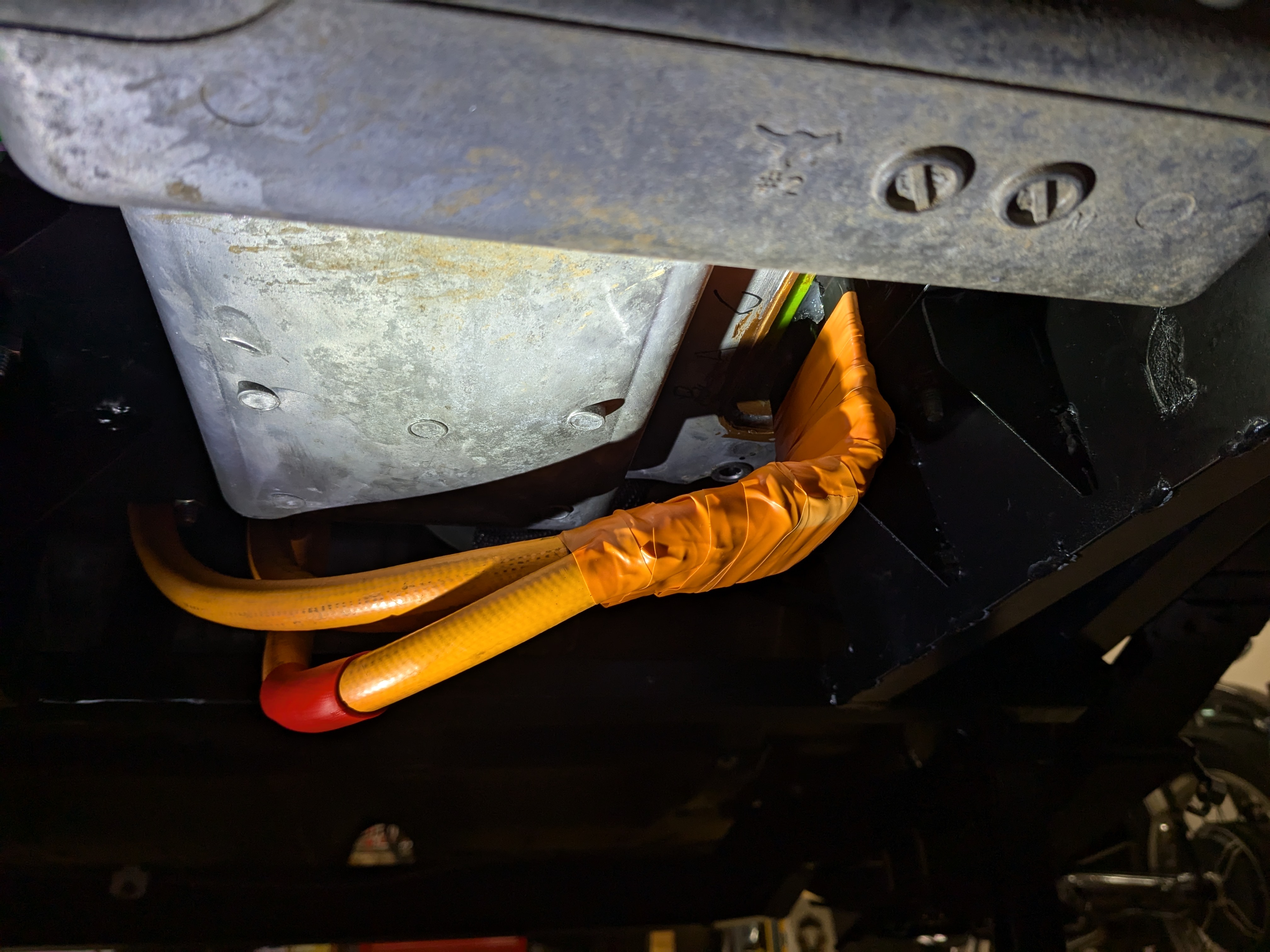
I also grounded all the shielded. After this photo was taken, I covered the exposed shielding with liquid electrical tape.
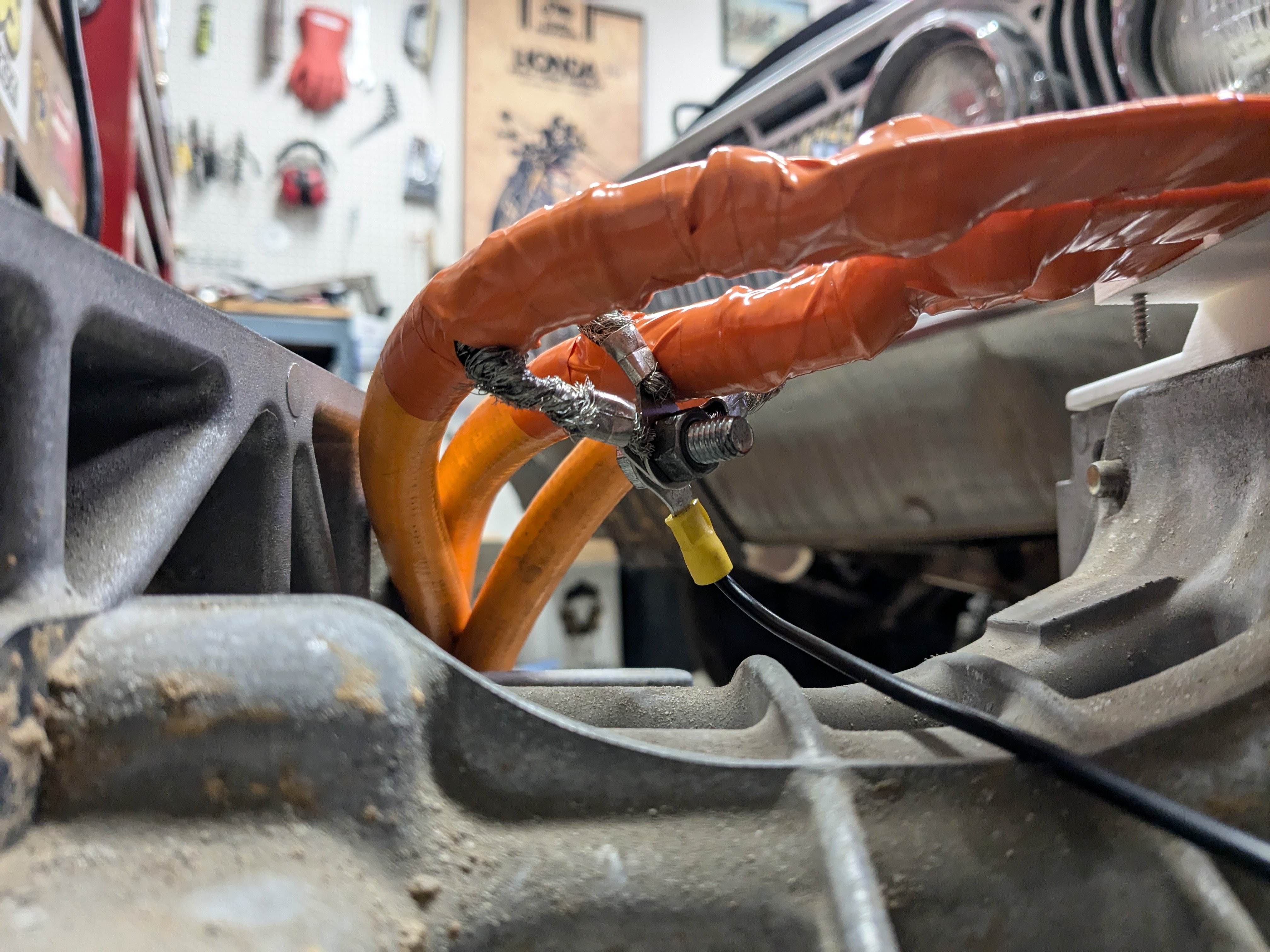
BTW, it is absolutely necessary to use shielded cable for these three cables. We're dealing with AC current between the inverter and the motor (it's an AC motor, and the inverter changes the DC current from the battery to AC) and AC current causes a lot more electrical electricomagnetic interference (EMI). Enough to cause problems with the CAN-bus wires.
Now to do the inverter before it's mounted in place.
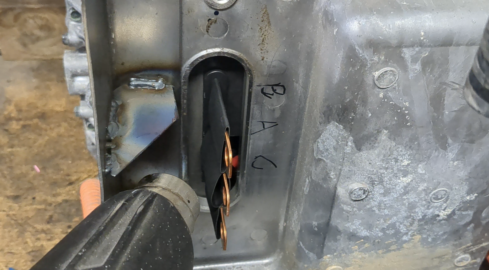
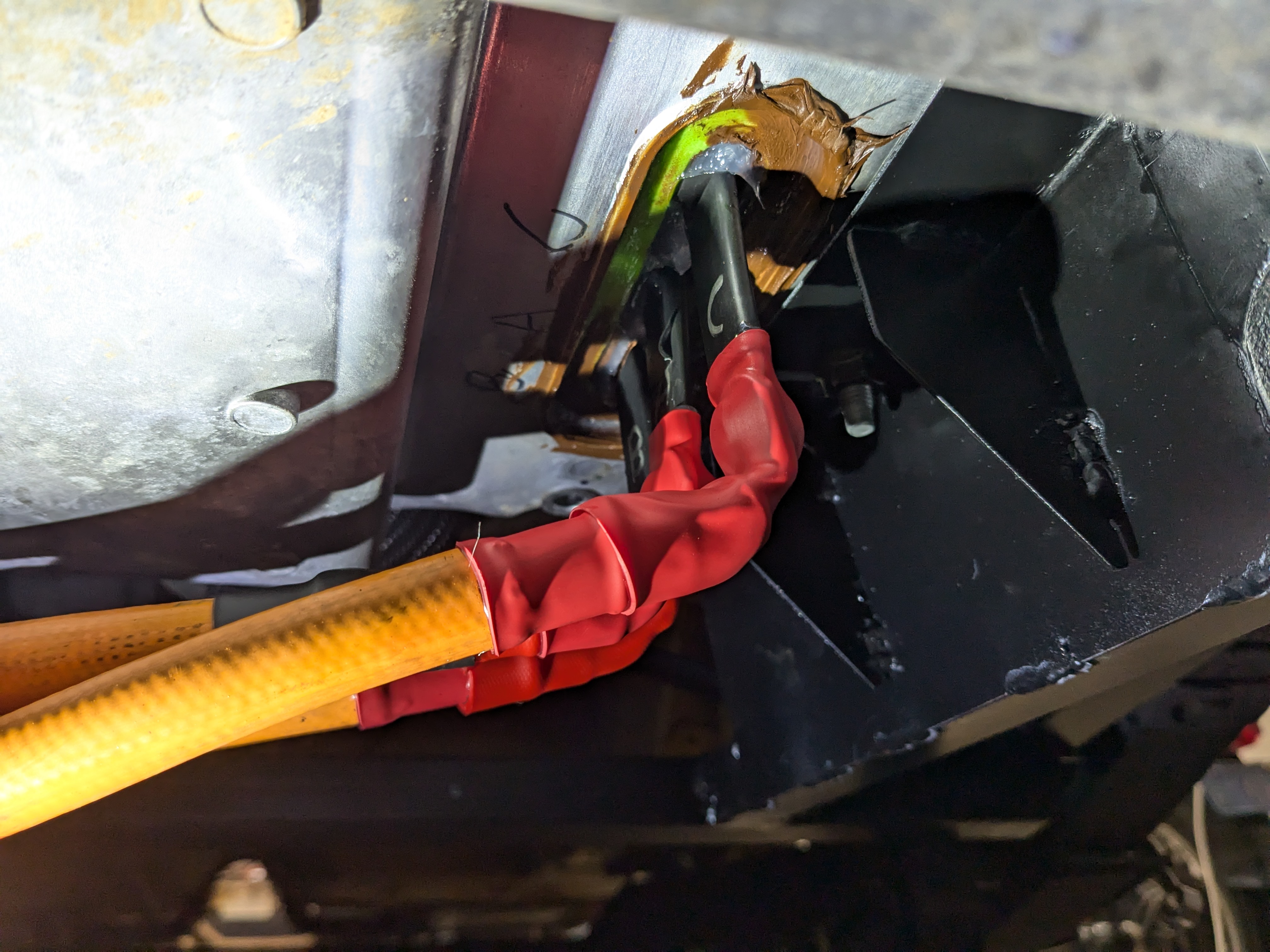
There's just a little bit of an opening into the inverter case (by the C label in the photo above). But rather than spend more money on another 3d-printed part, I made a piece from a nylon cutting board (don't tell my wife!) to seal it up. All the brown stuff is liquid gasket maker.
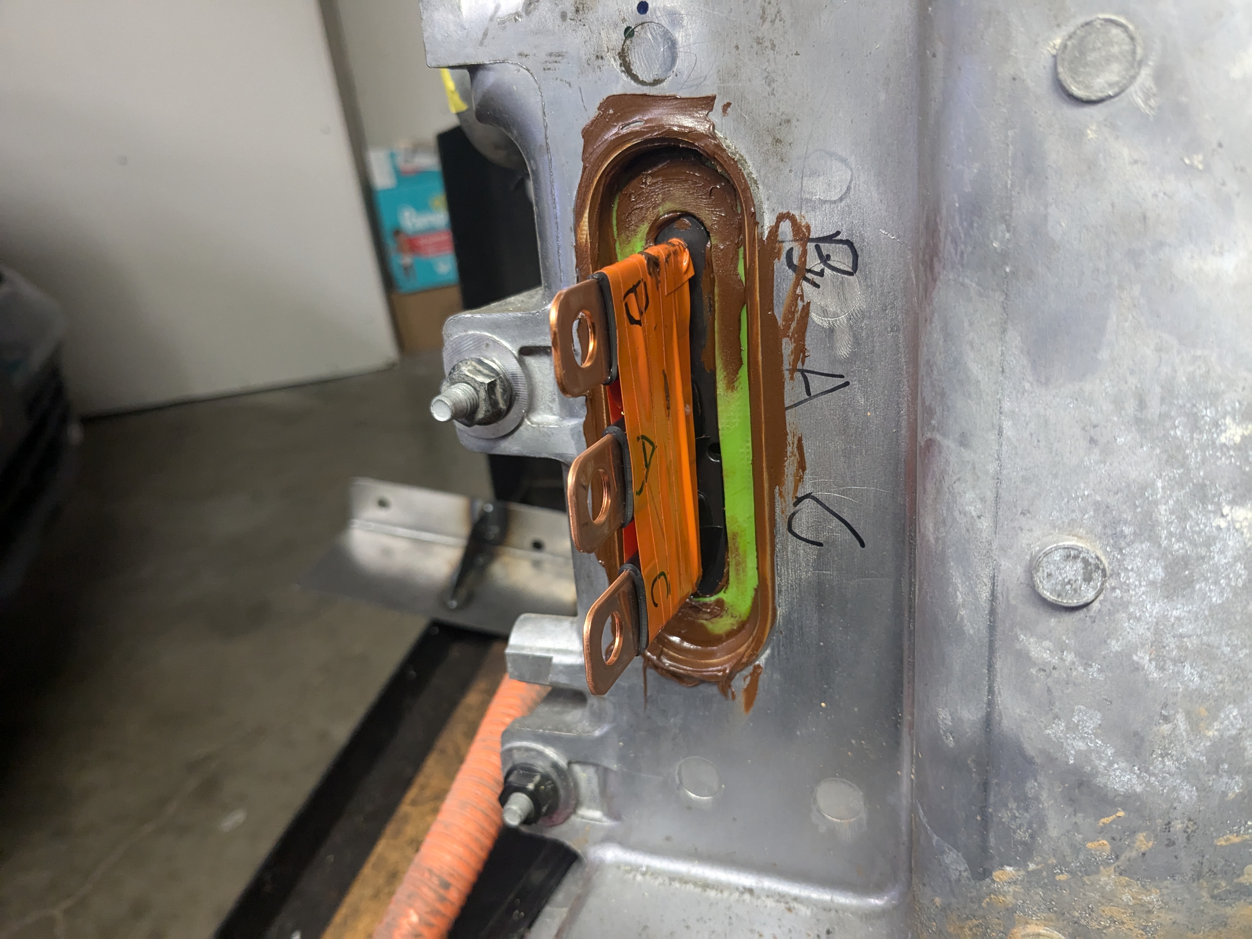
The reason for the "B A C" labels is to make sure I make the right connections. I had to swap two connections (A and B) to make the motor spin in the opposite direction than from the factory. This is because I mounted the motor backwards to make it fit better.
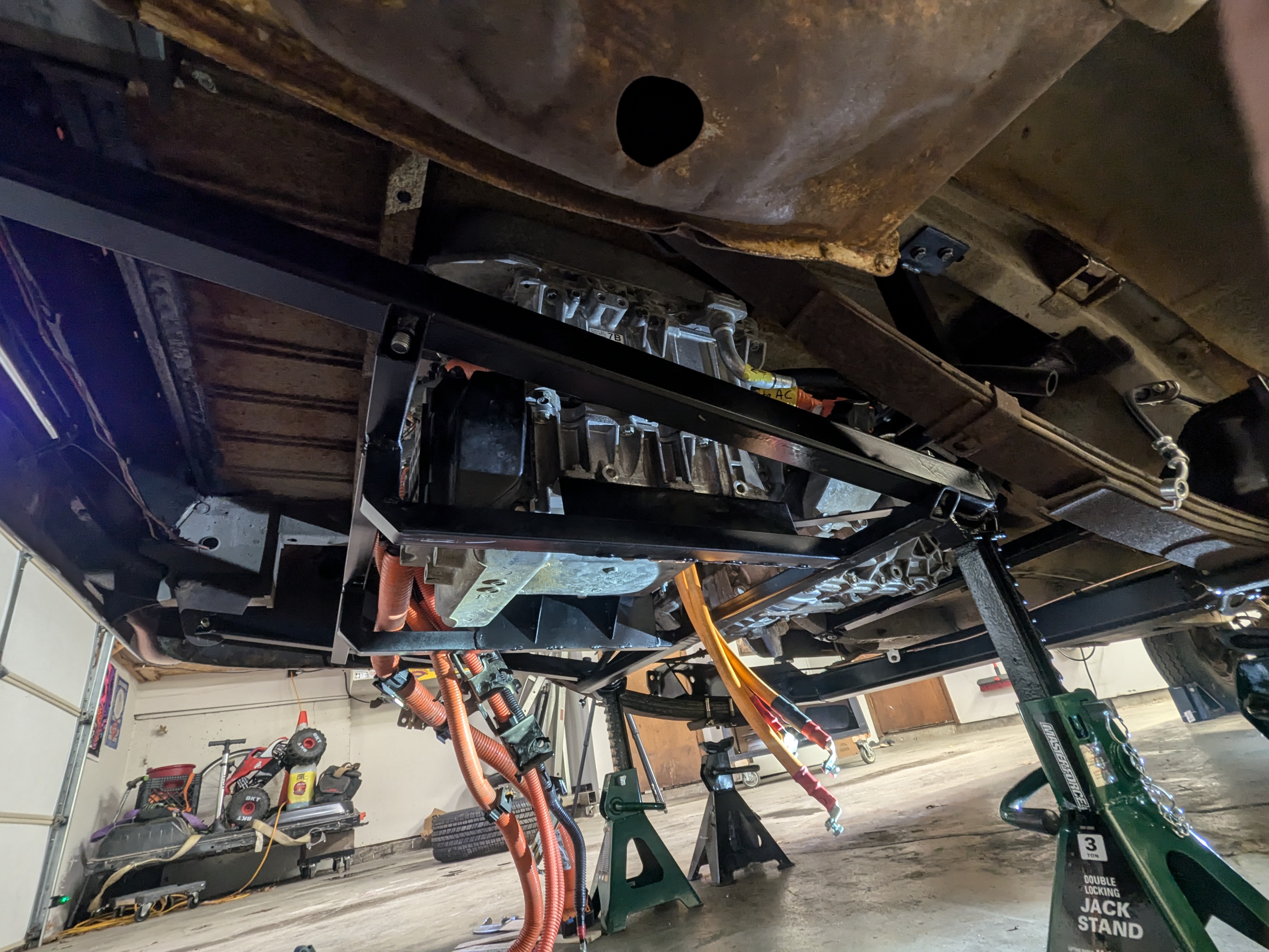
Now I could mount the inverter, motor, and then finish the connections.
Again, I used just a drop of threadlocker. And I'm using the heatshrink from EV West, it truly is some very tough stuff.
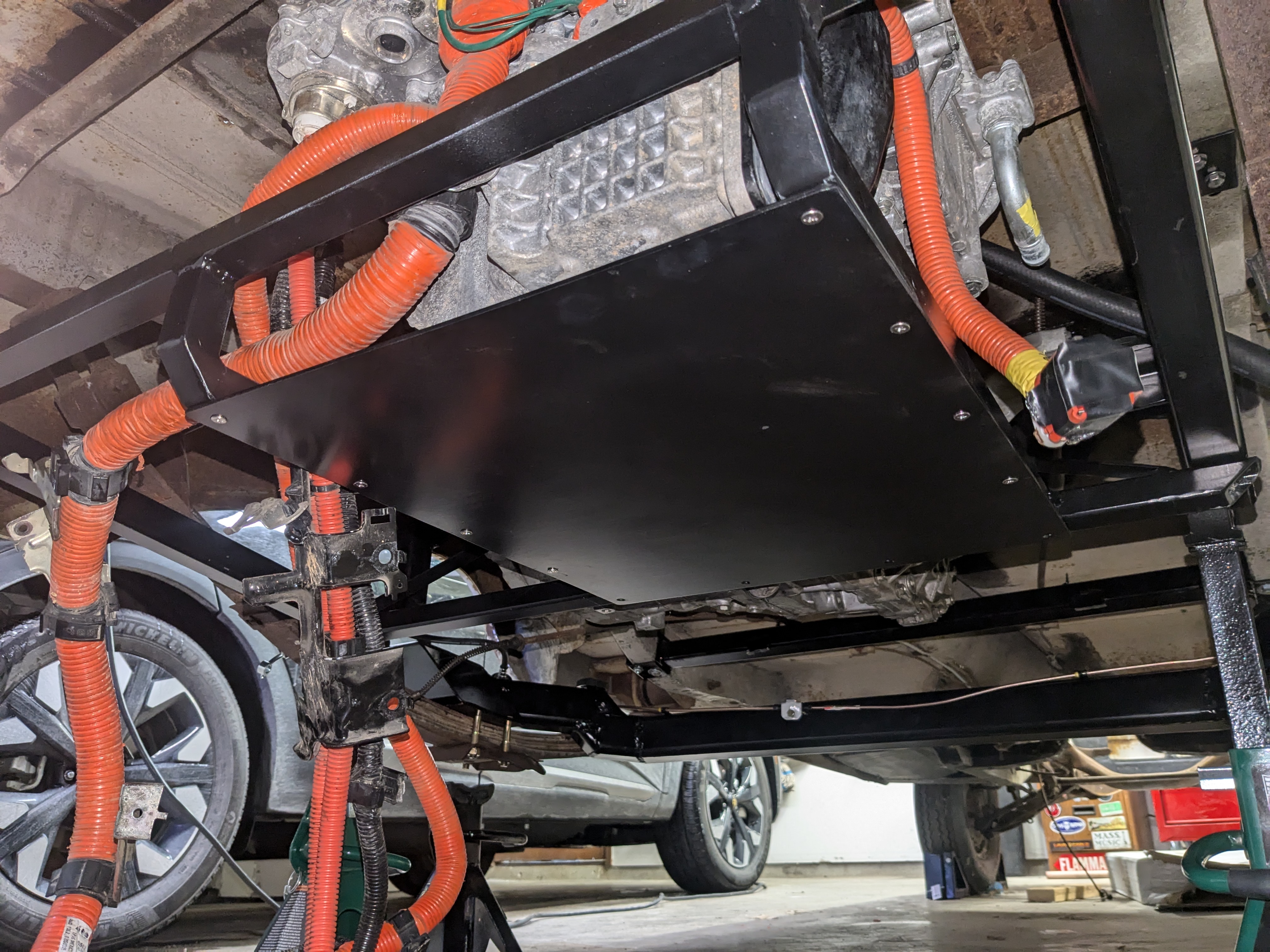
I added a 1/8" steel plate for skid protection for the inverter as well as to protect the cables. It also supports the HV cables a little so they're not dangling, which might eventually cause the bus bars to fatigue and crack.
That's it for the high-voltage cables, now lets do the charge ports!
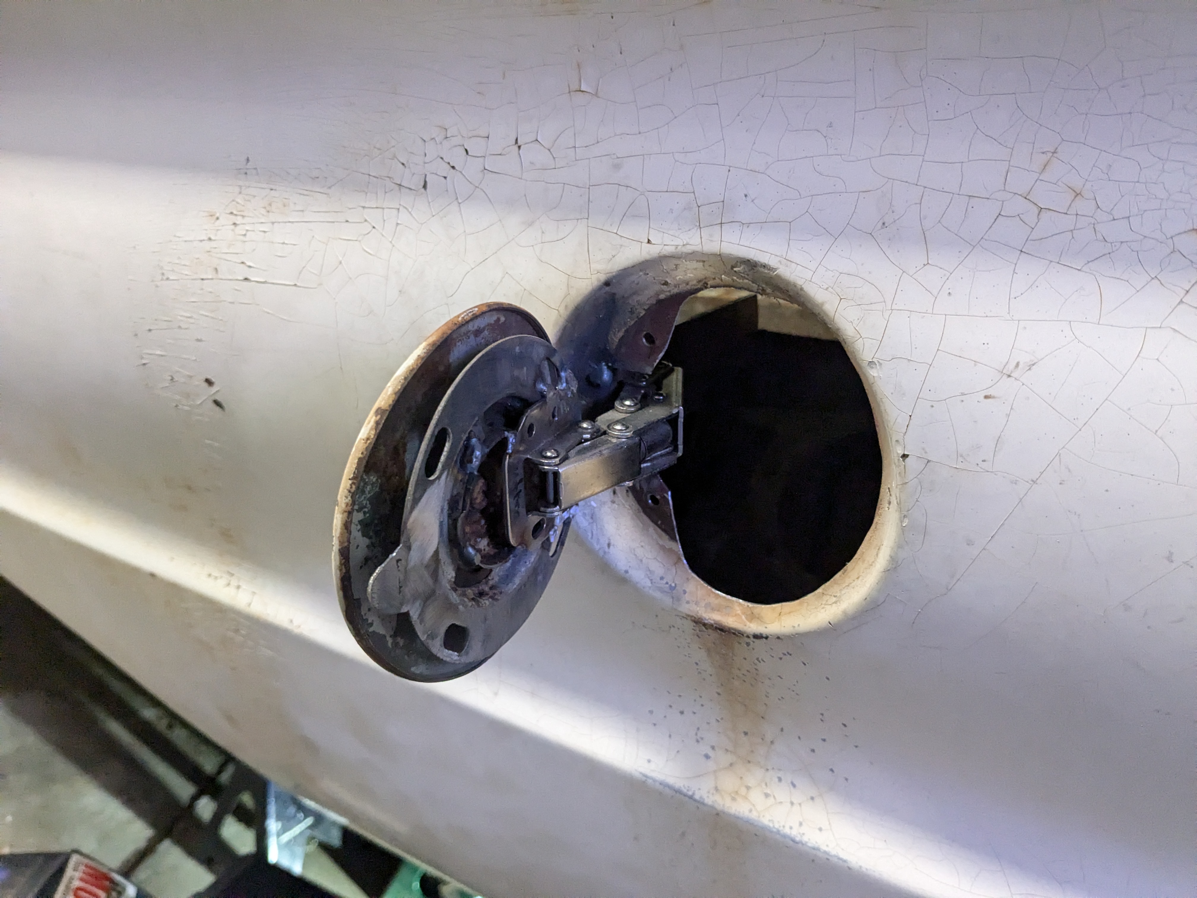
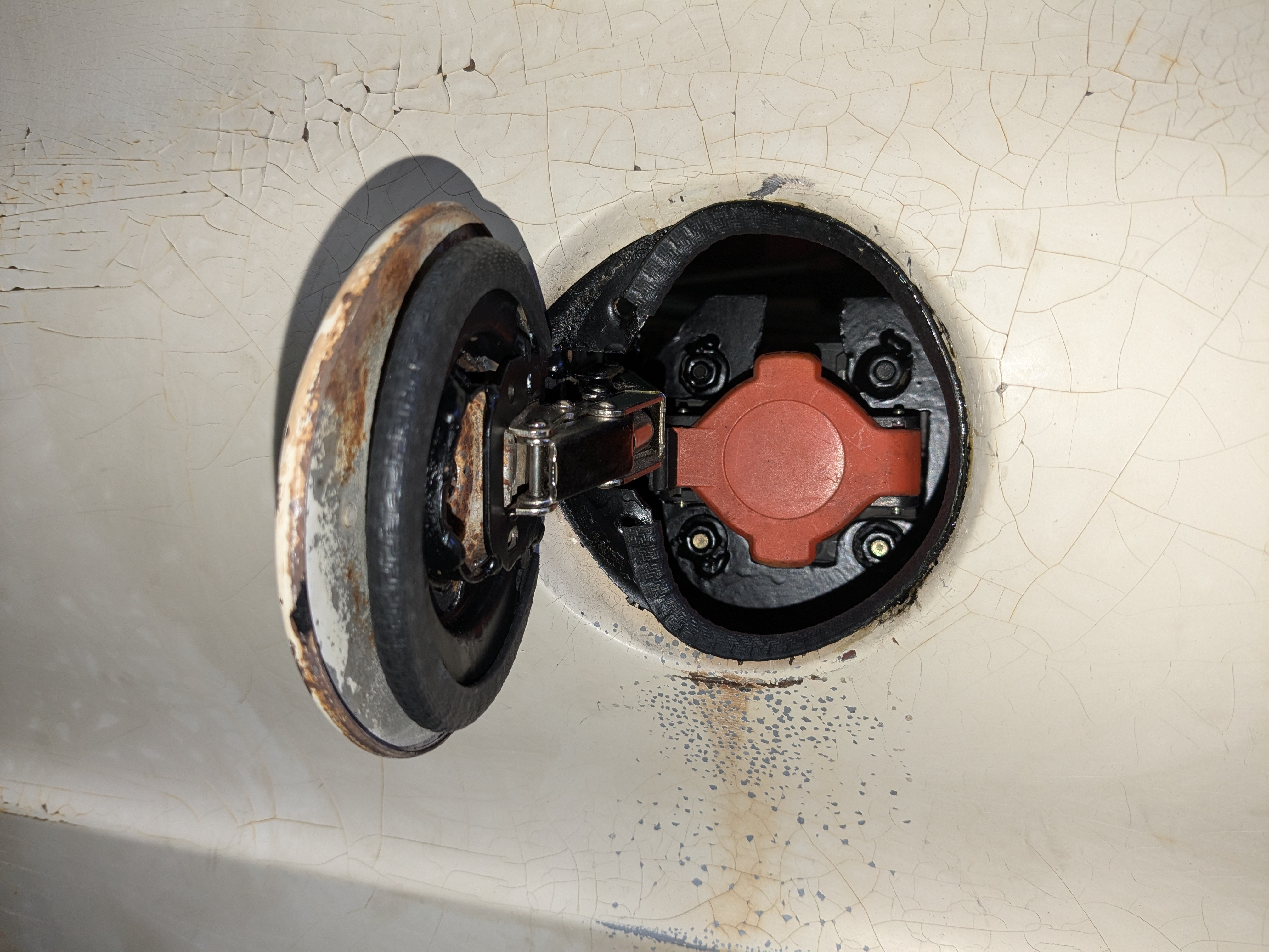
Here's where I had to get a little create. It's tradition on EV conversion to use the location of the gas filler neck for the charge port, but usually there's a pop-out door that covers it up. But not true with this old car, instead the gas cap was also the exterior of the car.
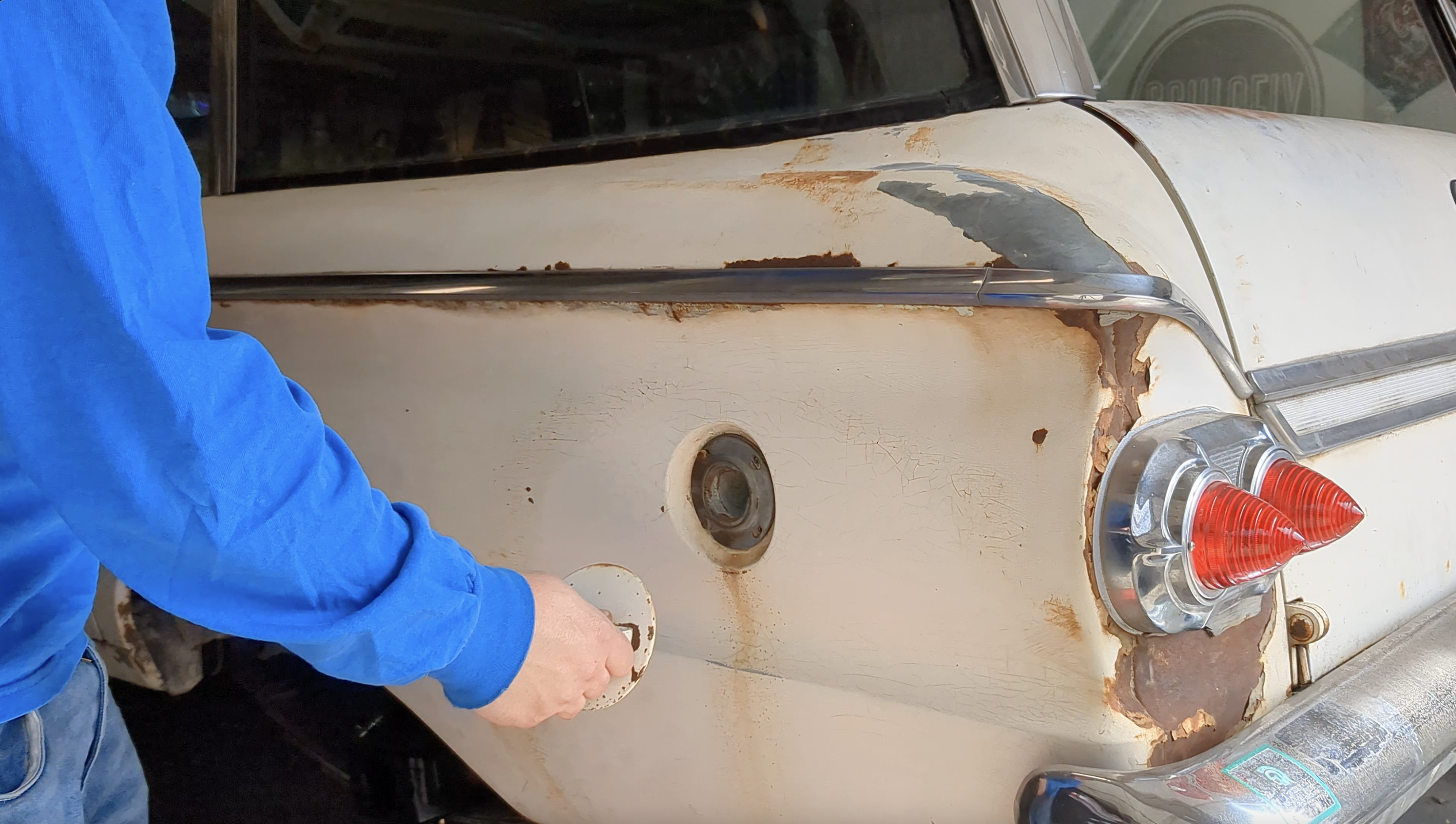
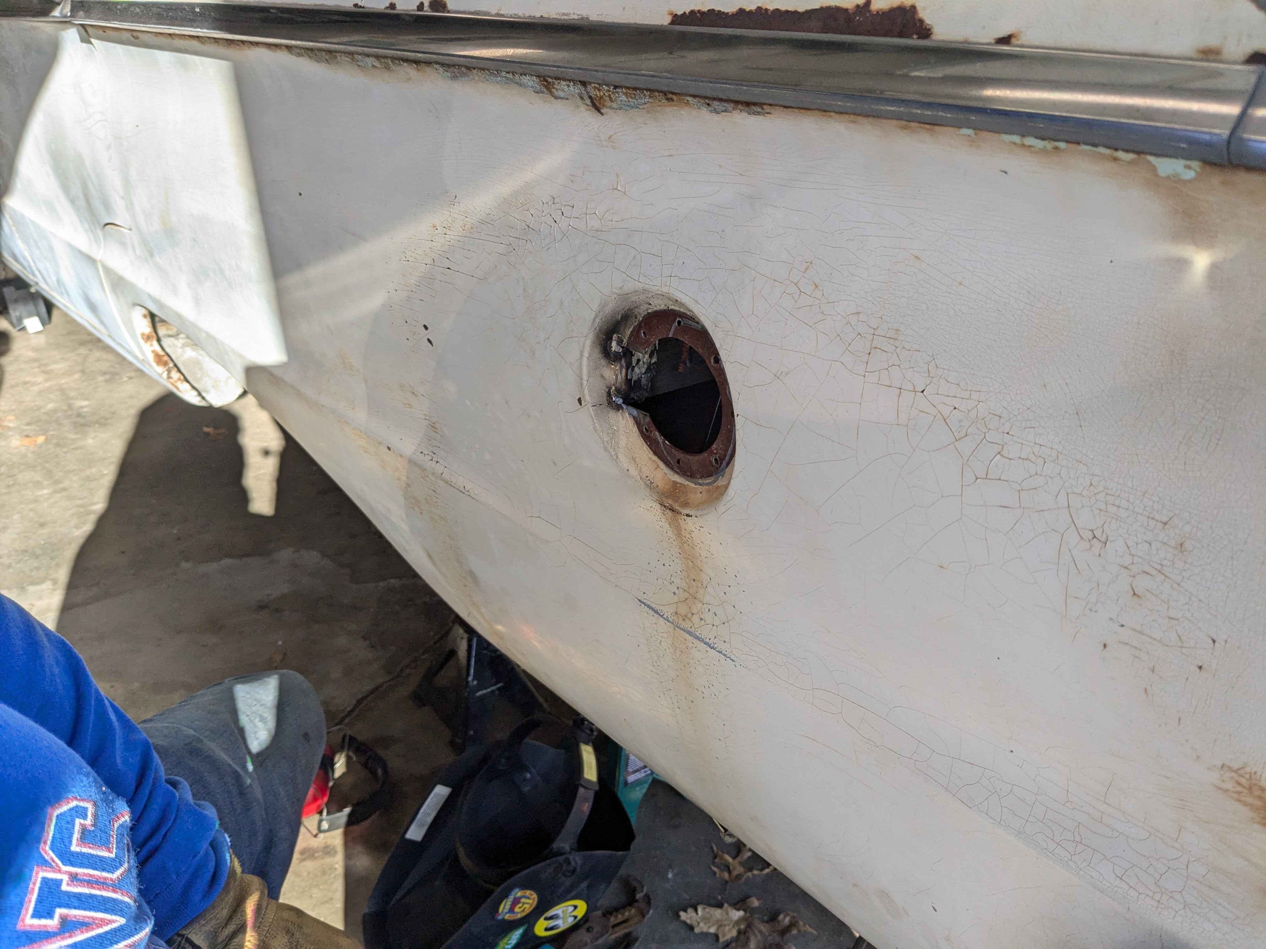
With the gas cap unscrewed and the filler neck removed, I tried fitting the J1772 plug into the hole but it couldn't fit. So I started cutting!
Here's the plan:
- Convert the gas cap into a flip-open door, and use a hidden hinge
- Enlarge the hole for the J1772 plug
- Mount the charge port inside the body panel
I was searching the net for a good fuel filler door hinge I could use - Miata? Jeep? - and then started looking at aftermarket hot-rod stuff. I saw some very high dollar billet aluminum hinges and I thought to myself, "kind of looks like a cabinet hinge." BINGO!!
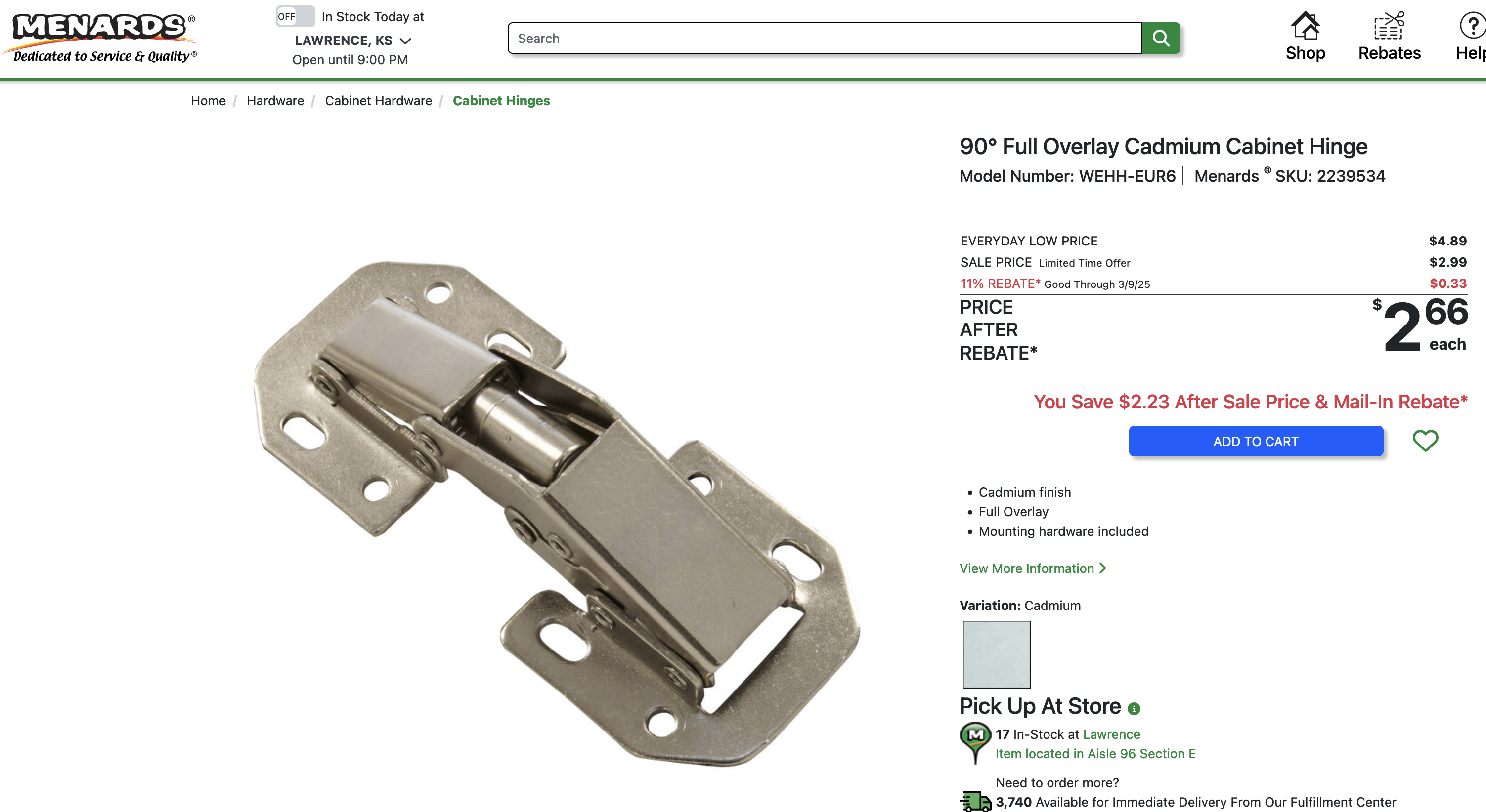
The spring weight is way to strong for the weight and length (leverage) of the gas cap, so it's a little stiff getting it open, but it's only $3 so I can't complain. $547 less than the aftermarket hot-rod stuff.
Thankfully I had great access from inside the cargo area of the wagon. There was a panel that could be removed to give to perfect access. Otherwise it would have been impossible.
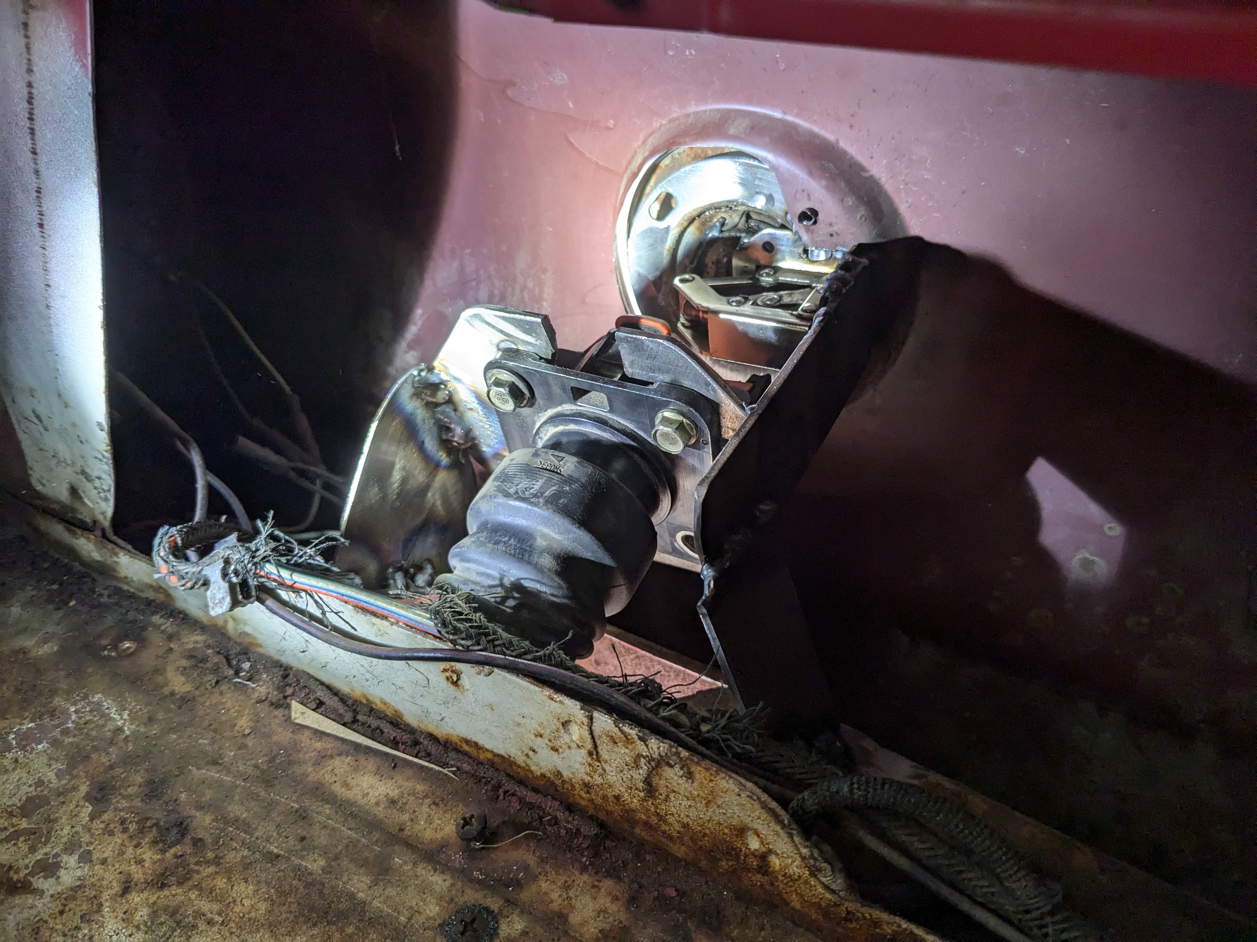
It has to be set back about an inch to clear the hinge when the door is closed. I finished it up with some flat black paint and some windlace to go around the edges of the sheet metal.
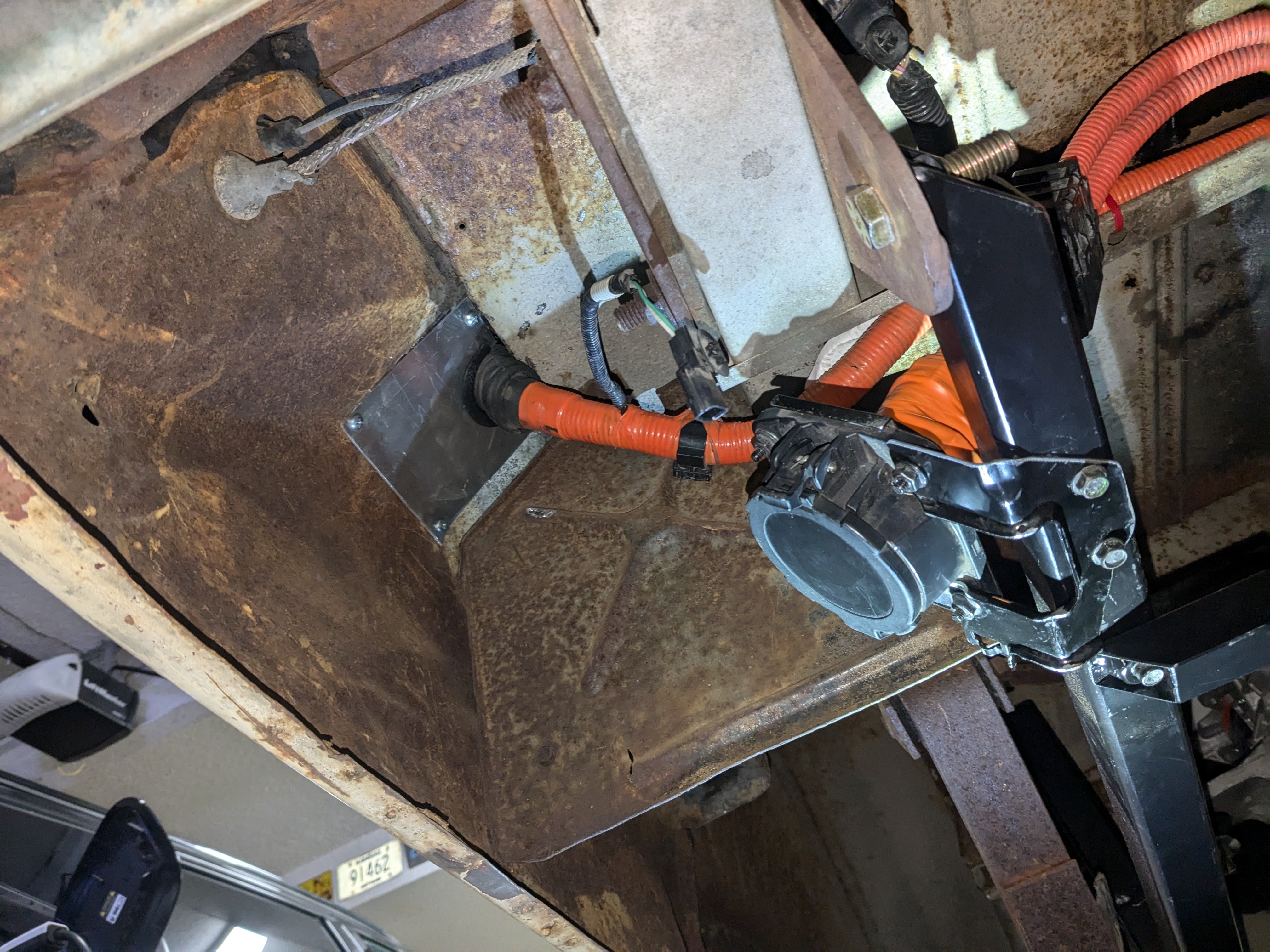
I also took care of another low hanging fruit (almost literally, as the two charge ports were dangling from the PDM and onto the floor below). I don't know if I'll use the fast charger port very often if at all, but it needed to be accessible but there was no good spot externally. Maybe behind the license plate but I would have had to cut a huge hole in the bumper and weaken it significantly. So I just mounted in behind the rear tire.
The only high-voltage wiring left to do is all related to the battery pack, so I'll include all of that in the battery pack chapter.
Thanks for reading!