What sets the build apart from 99% of other EV conversions is that I'm using a De Dion design for the rear axle. This will allow me to place the electric motor in the rear of the vehicle and use Nissan Leaf gearbox and CV shafts to send power to the rear wheels. This avoids not just the headache/expense of building/buying adapter plates and couplers to connect the electric motor to the old manual transmission, it also takes the weight* and efficiency loses of the old transmission and solid axle out of the equation. This will make for a lighter and more efficient vehicle. [*Edit: the original axle weighed 150 pounds, with the drum brakes and axle shafts and all. My new De Dion axle tube weighs 60 pounds, but that's without the CV shafts, brakes, and wheel hubs. In the end it might be a wash.]
A De Dion axle, compared to a traditional "live" axle, is like a "dead" axle. The axle shafts, in my case CV axle shafts, are outside of the axle tube. And the axle tube is in a long U shape so that a differential, engine, or in my case an electric motor, can be chassis mounted between the rear wheels.
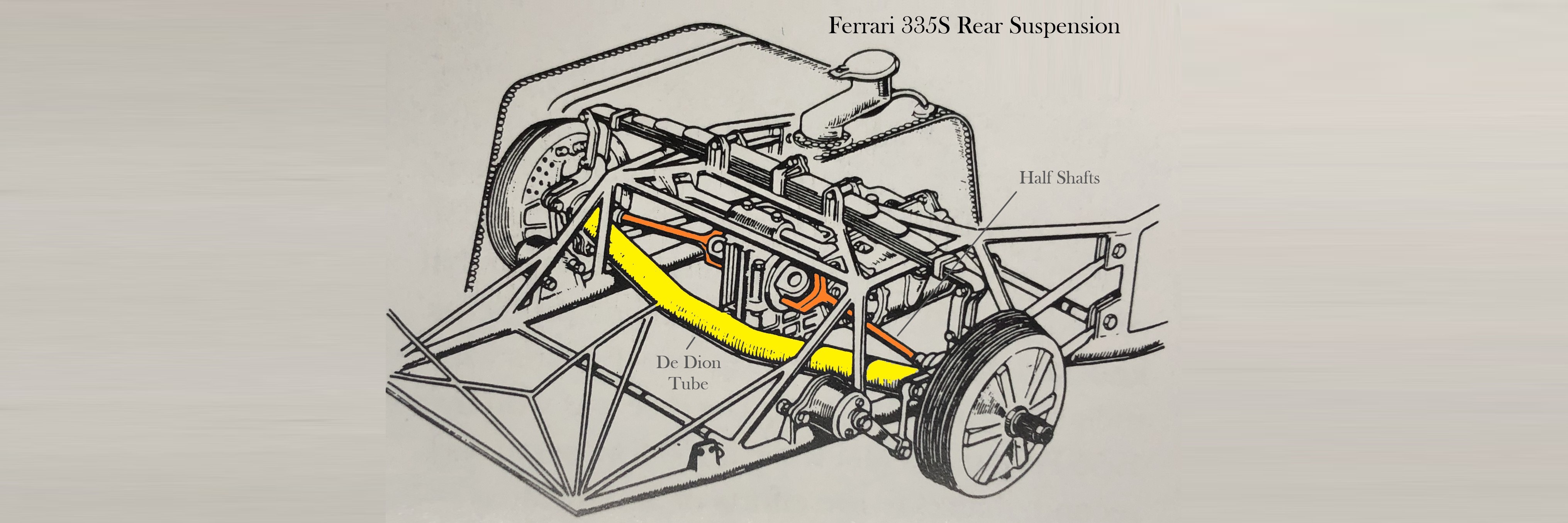
The design was never common, but it found its way onto very old race cars by Ferrari, Alfa Romeo, and others. For production vehicles, only a few examples can be found, such as the Volvo 300 series. And, notable for this EV conversion project, it was also used by Ford for their electric Ranger from 1998 to 2001.
Enough with the history lesson, lets get started building the damn thing.
Here's my YouTube video that shows everything, but I'll also post all the photos below and provide as much details as I can.
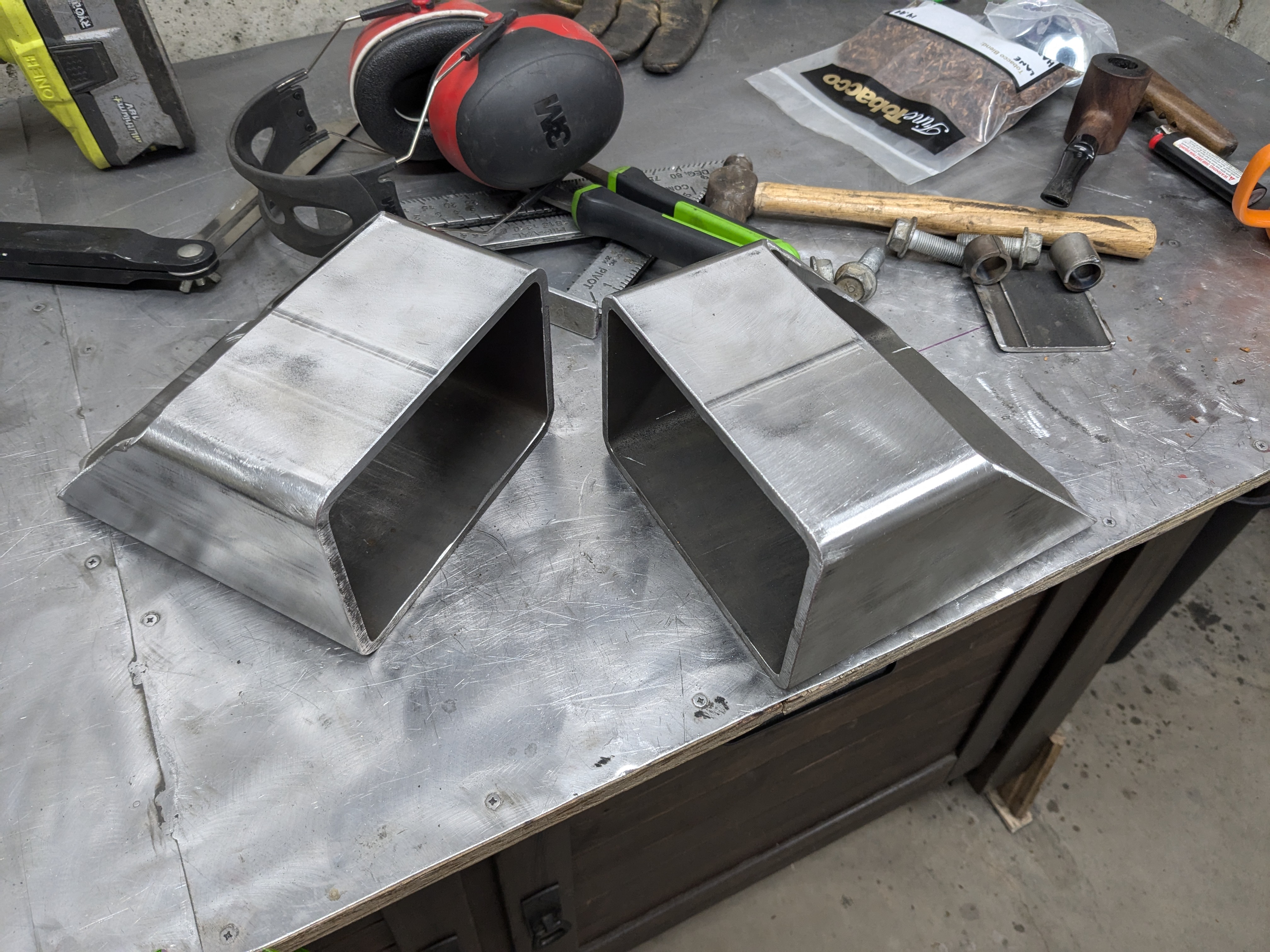
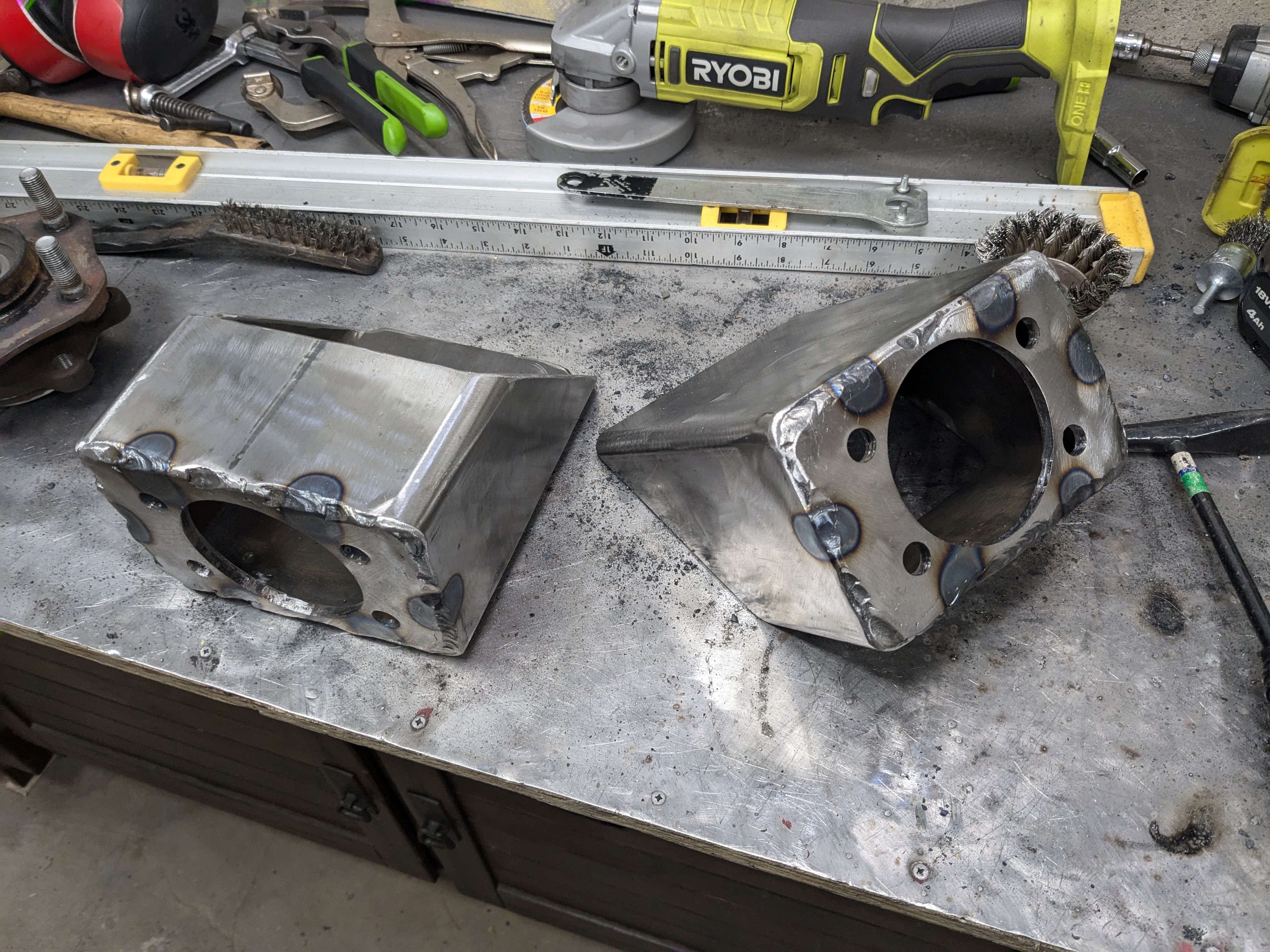
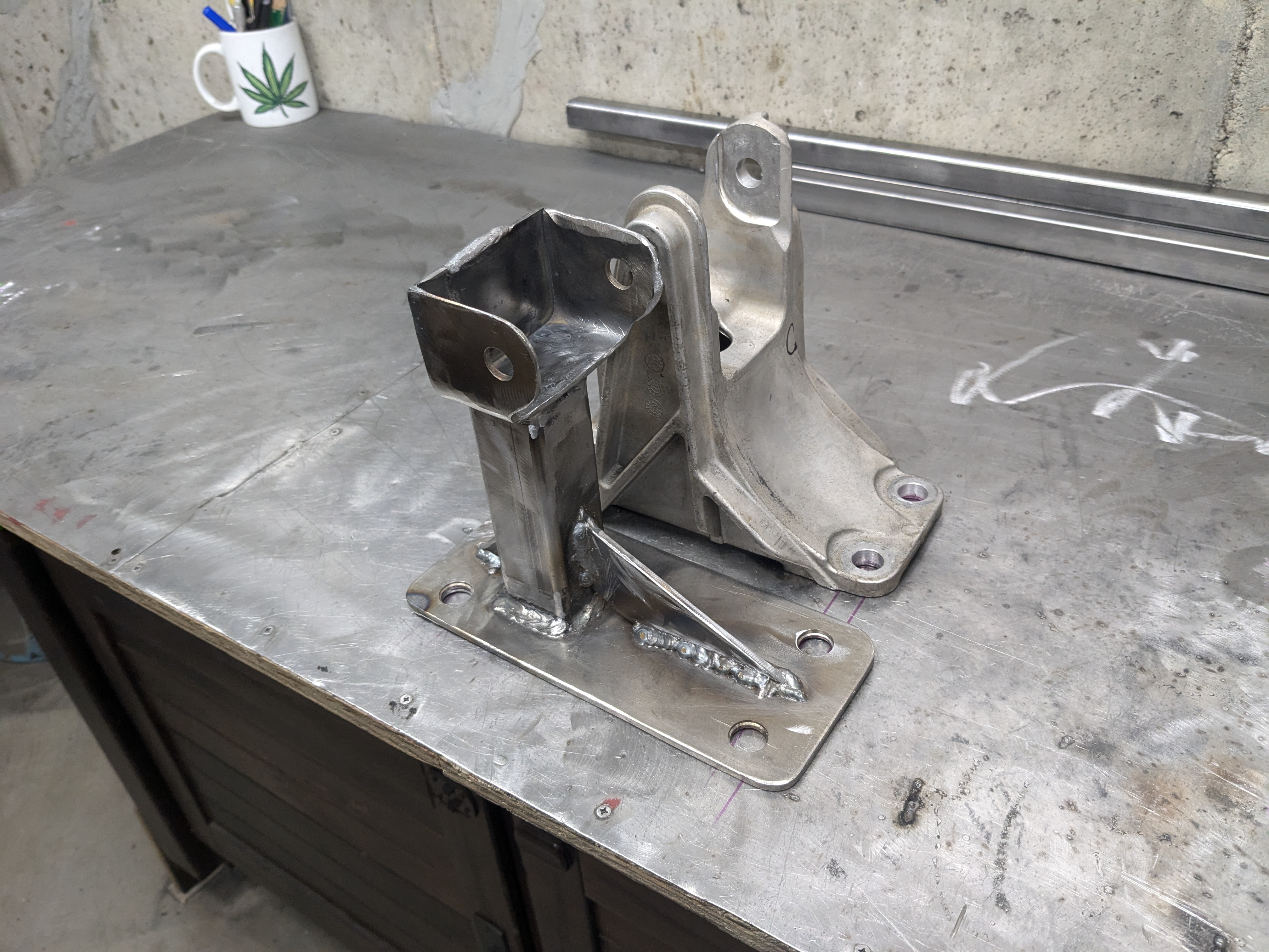
My first task was to create the ends of the axle tube. For this I used 4"x6" box tube sections, 1/4" wall. In hind site, I wish I used 5x5 box tube, this would have help fitting the brakes a little easier (more on the brakes later). And, honestly, using round tube wouldn't have been much more difficult either.
And I decided to have SendCutSend cut out the flange for the hubs. If I had a lathe I could have done it myself, which sadly I've said at least 4 times so far on this project. Maybe I need to buy a lathe.
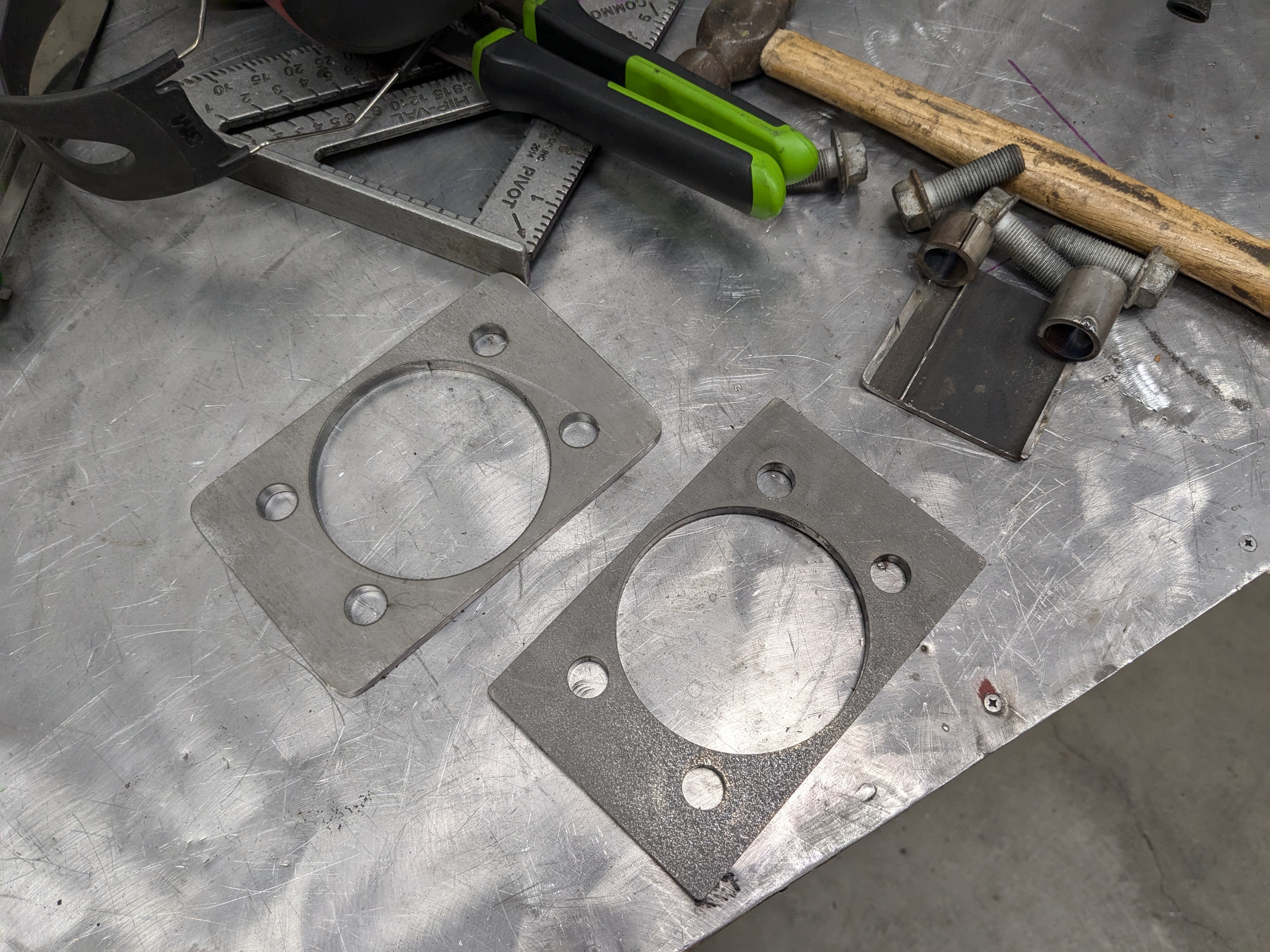
They needed to be welded to the box tub section perfectly parrallel in all dimensions, otherwise the wheels would be out of alignment. I used a very square wooden jib and many clamps while I tack welded them together with my MIG welder.
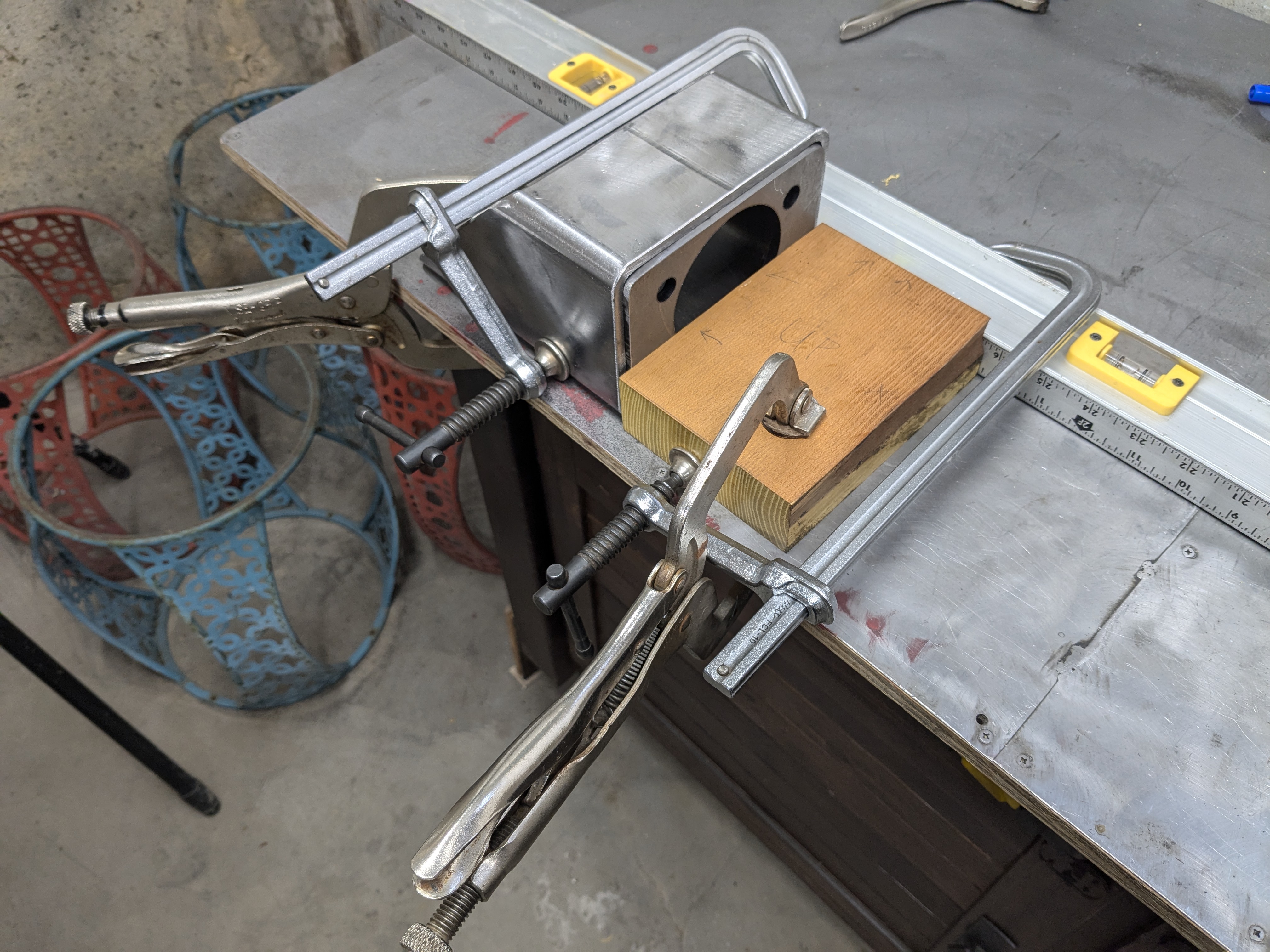
Then I welded them solid with my stick welder, as my MIG machine wasn't powerful enough for 1/4" plate.
While I still had the two end pieces on my bench, I wanted to get the brakes sorted out. I'm using 2005 Honda Accord brakes because they've there right size, lug pattern, and because they have a handy feature for a cable-pulled parking brake.
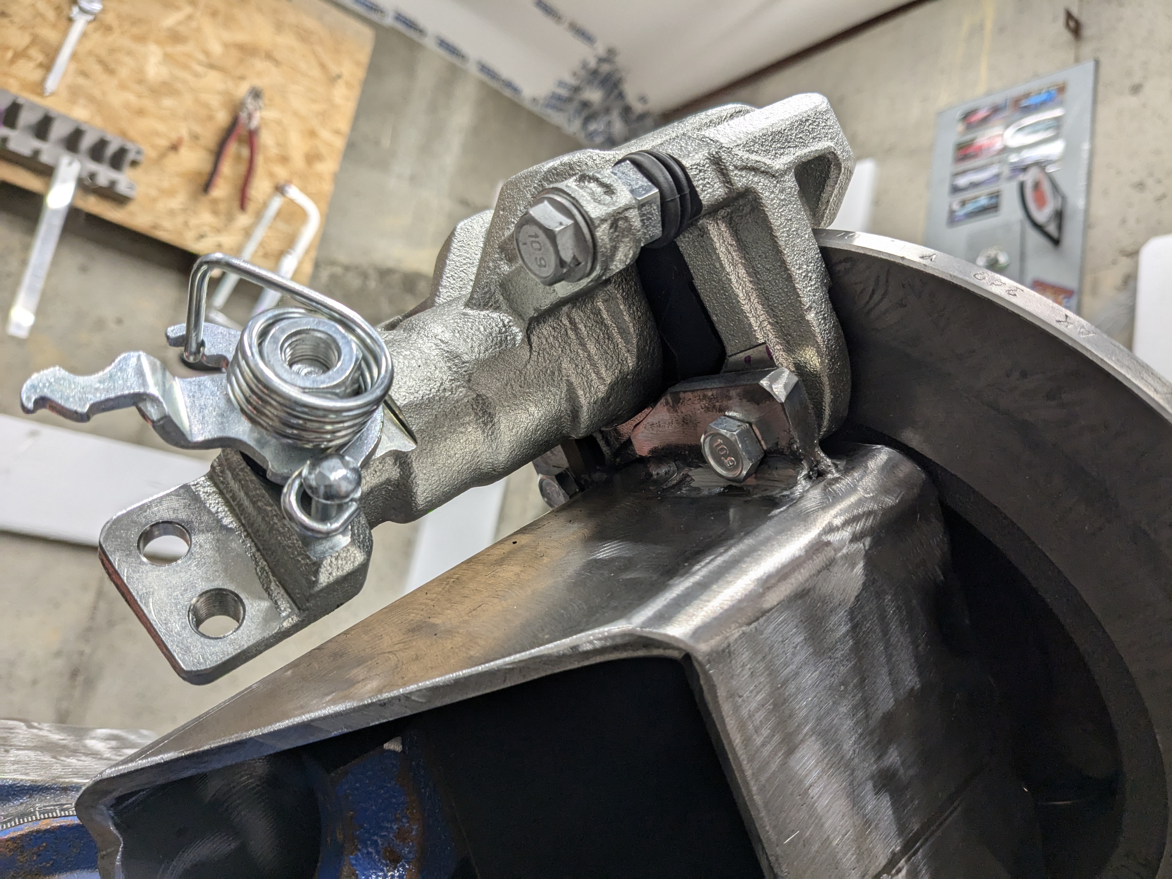
I welded on tabs for mounting the calipers onto the box tube, and to get them perfectly aligned with the brake rotors, I bolted the hubs onto the box tube, bolted the rotors on the the hubs, and then placed the calipers (with brake pads on) over the rotors, bolted the metal tabs to the rotors, tack welded them on, dissasembled everything, and then welded on the tabs with the stick welder.
I had to modify the calipers a little to get them closer to the rotors to get more of the brake pads to engage. This is why I said earlier in this post that would recommend a 5x5 tube over a 4x6 that I used. And I couldn't put the brakes on the bottom of the 4x6 tube because they would be in danger of hitting rocks and snow and stuff, and I couldn't put them on top because that would essentially turn them into bump stops with the unibody frame rails.

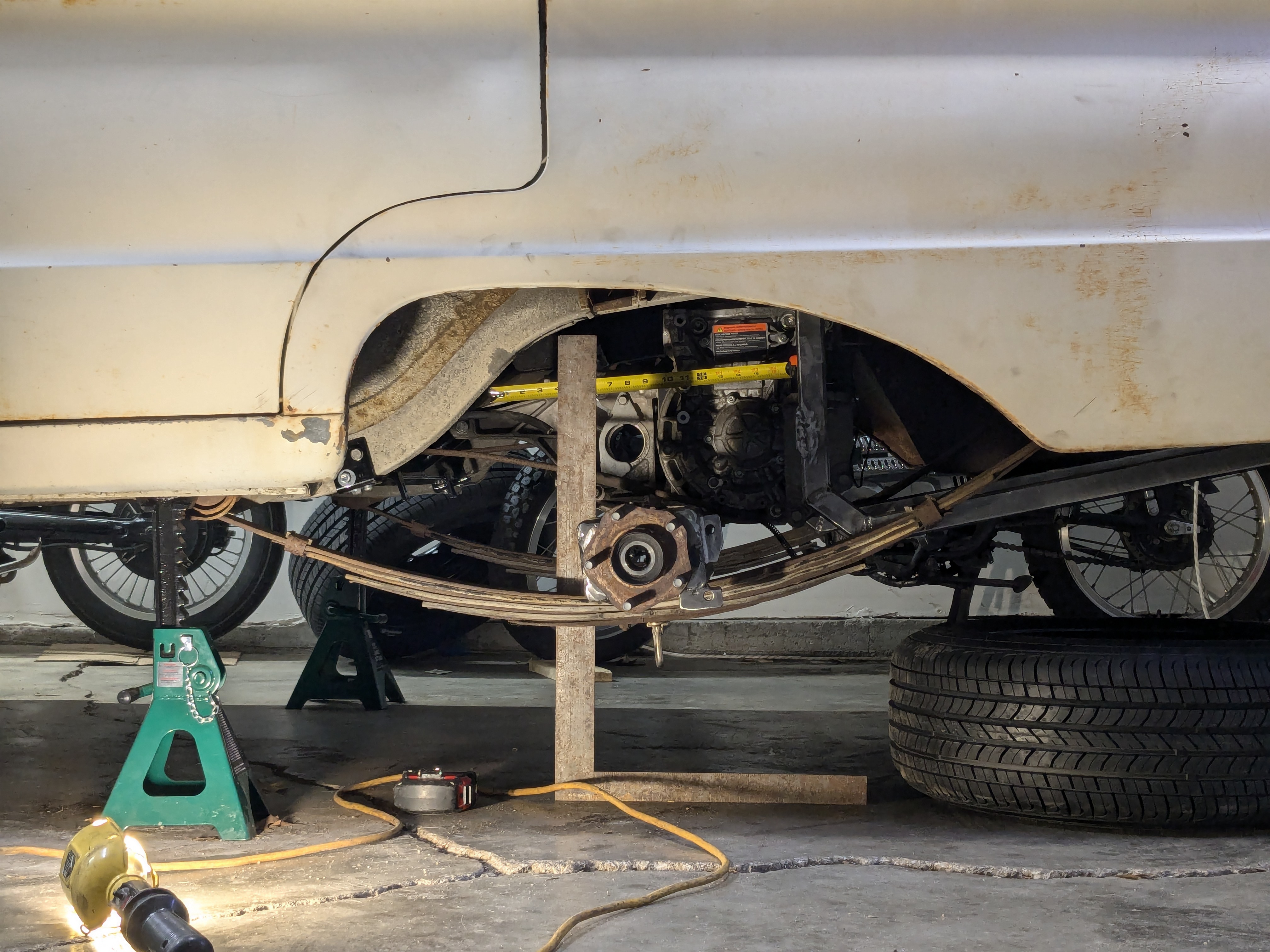
Before I could build the axle tube connecting the two end pieces, I needed to know how long it needed to be and how much space was needed to clear the motor and gearbox.
So I clamped on the end pieces onto the leaf springs, bolted on the hubs and wheels, and adjusted them until they where in just the right spot. One cool thing about building your own axle is you can set the wheel track to exactly whats needed. I used a tape measure to measure the distance between the inner mounting surfaces on the steel wheels, this will be the length of the axle tube.
I also marked where to drill the holes for the locating pins on the leaf spring packs. I actually positioned them so the wheels would be about 1.5" further back than the stock location, this gave me more room for the slightly larger tires I'm using than stock had.
In the previous blog post for this project, I decided to mount the motor in the reverse orientation (wires will be crossed so that it's actually driving forward) so this means I'll have to have the tube go in front of the motor and not behind. And now with both the axle ends clamped in place and the motor mounted, I could take my measurement. I just eye balled it, it doesn't have to be precise.
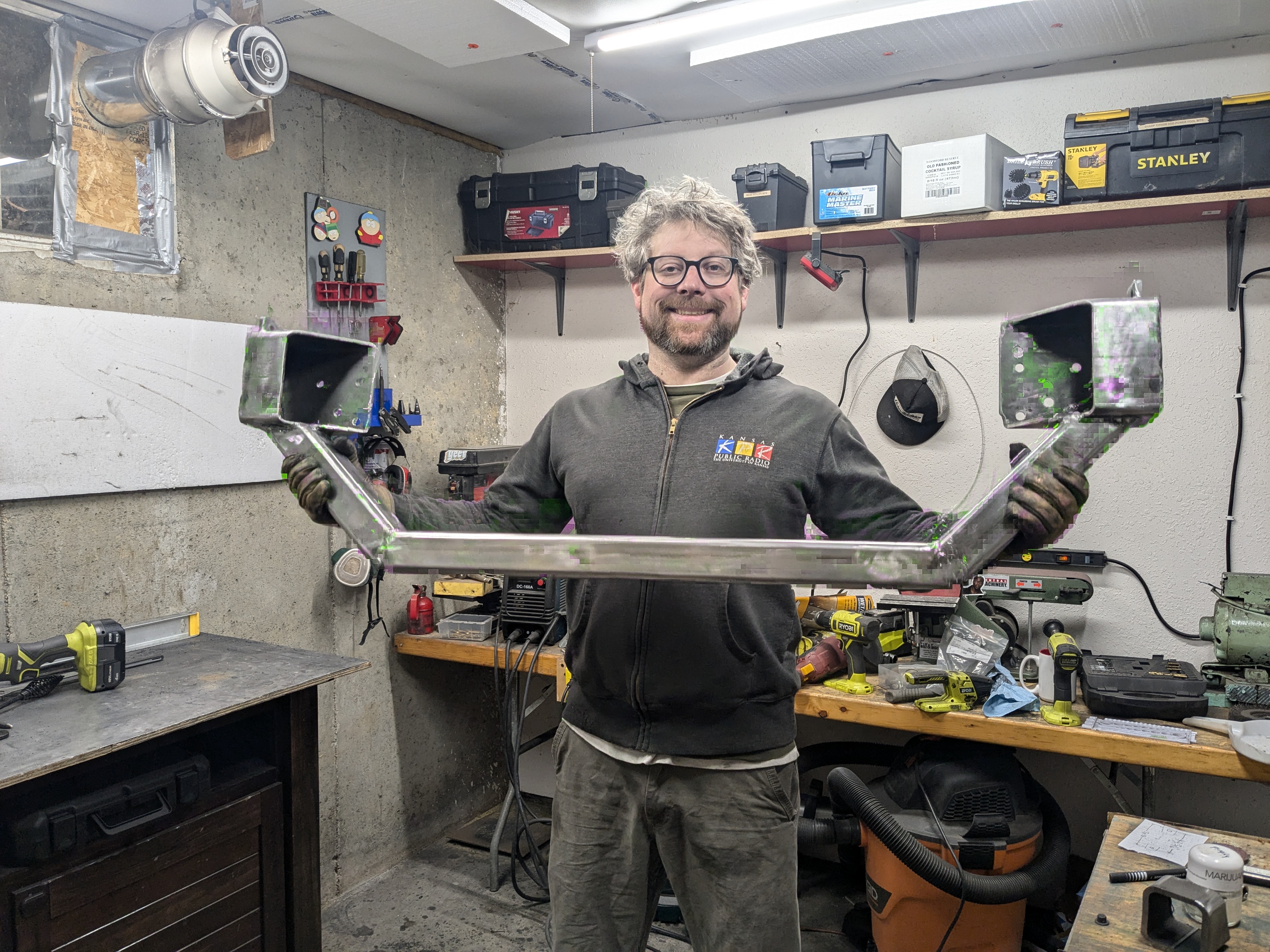
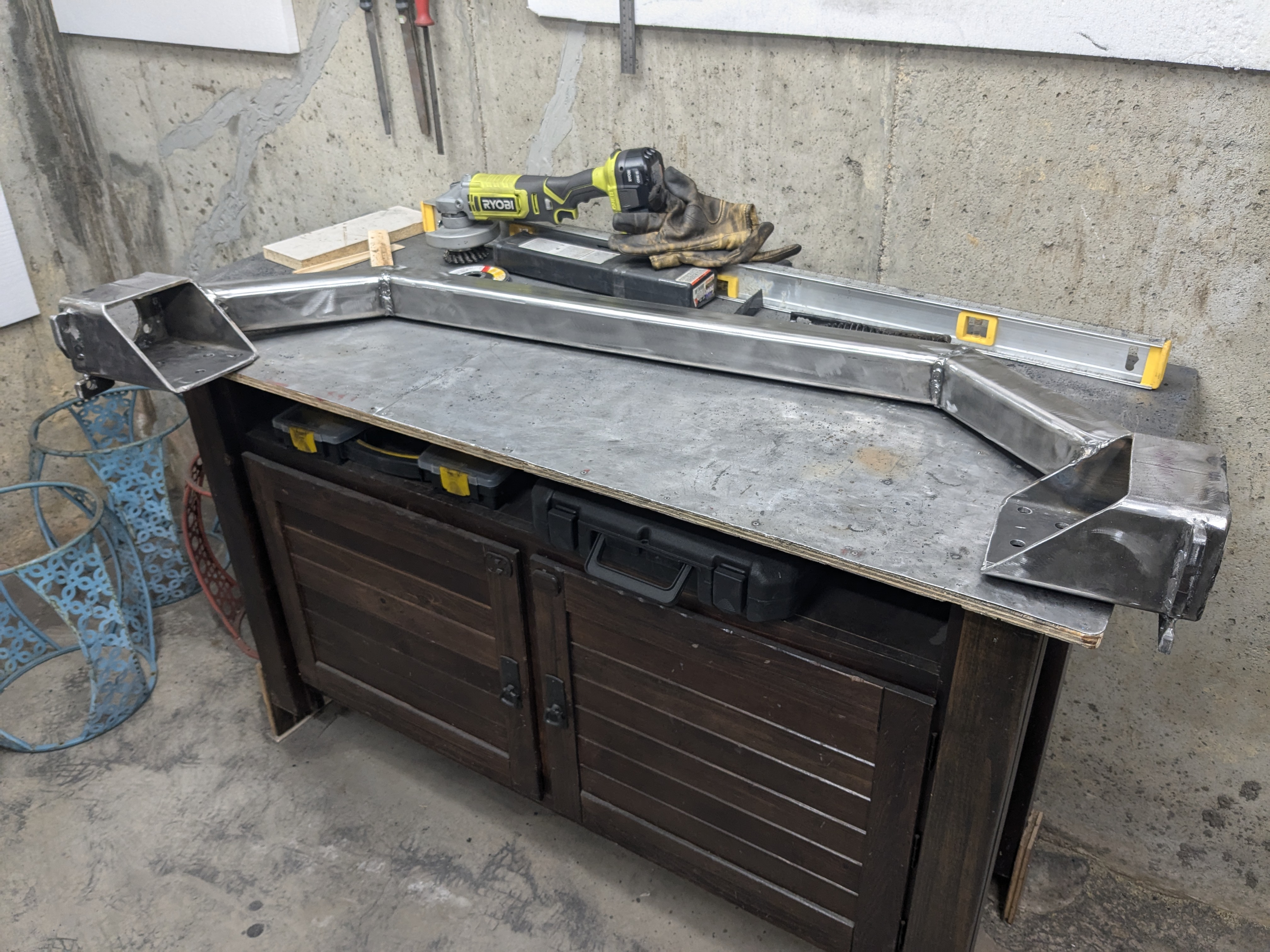
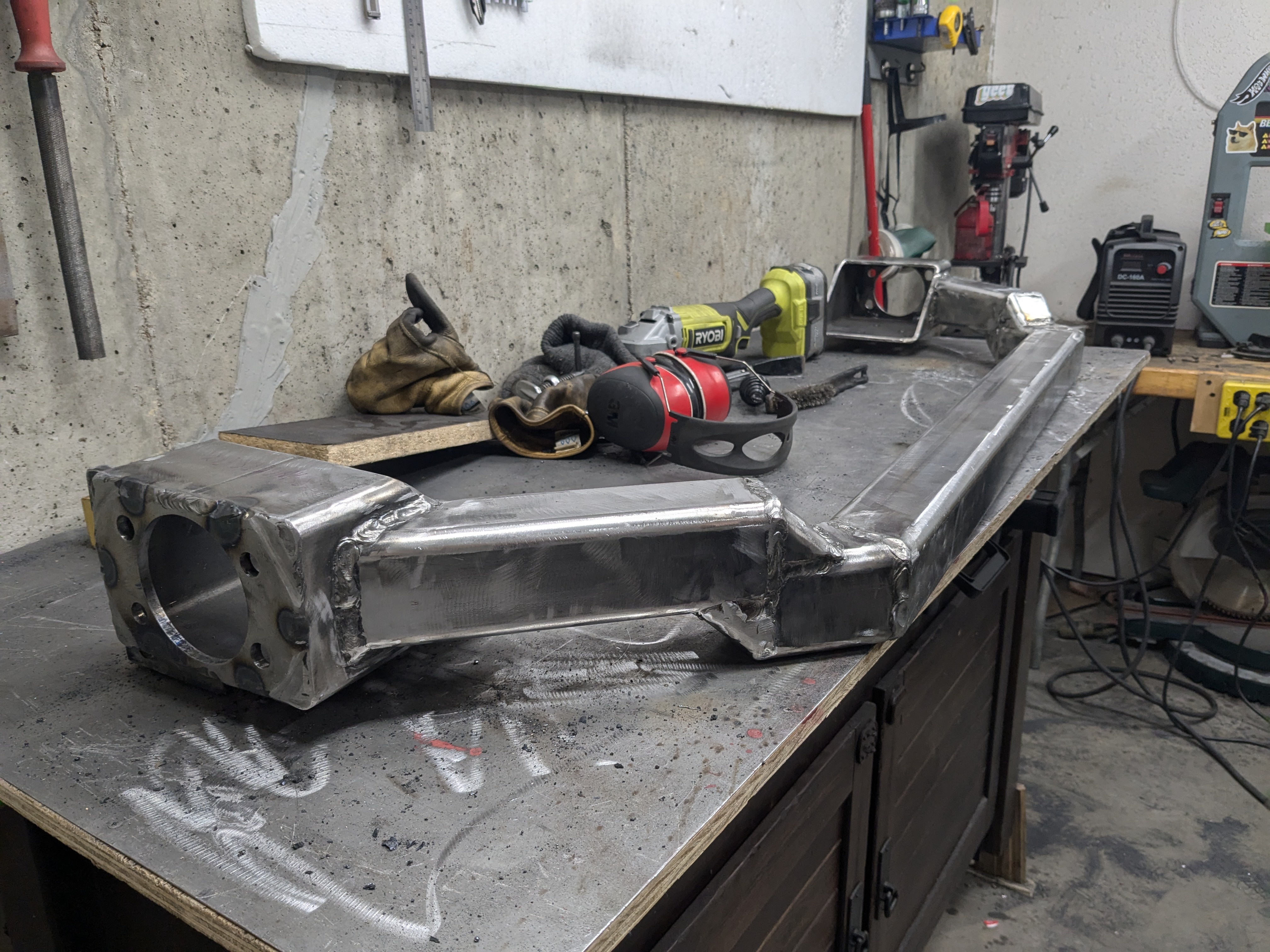
Finally, it was time to build the axle tube. My cheapo welding table was not flat at all, which would have been a problem and caused the wheels to not be aligned, so I used a piece of butcherblock countertop. It's not *perfectly* flat but it's good enough for me. I also used a good straight edge and many clamps to make sure the hub mounting surfaces where "perfectly" parallel with each other. Possible because I made sure the flange surface was totally perpendicular to the box tube when welding it together.
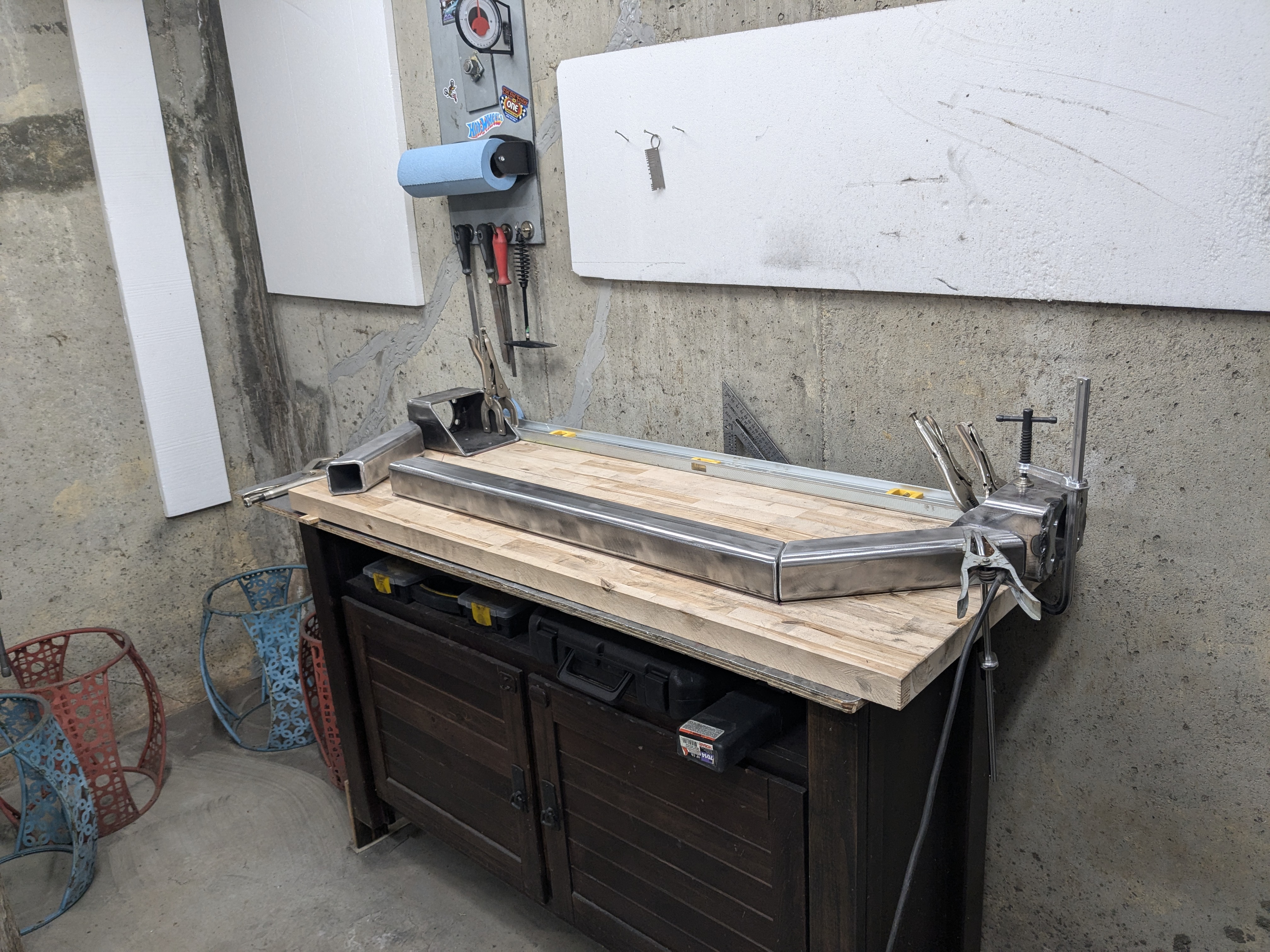
I'm using 2.5"x2.5" square tube, 1/4" wall. I'm not an engineer, so I don't know if this design will fail. If it does, I'll just rebuild it but with round tube or something.
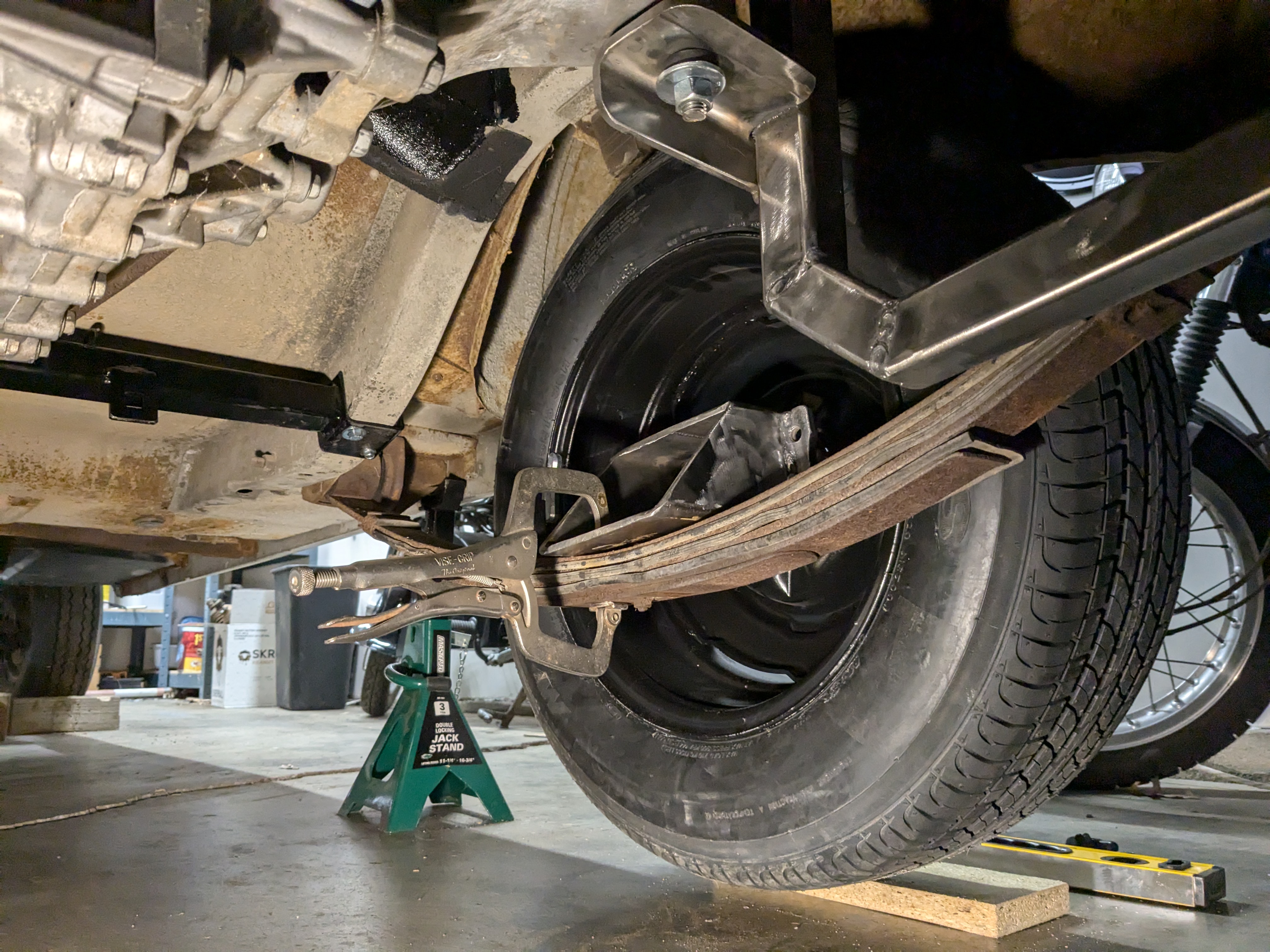
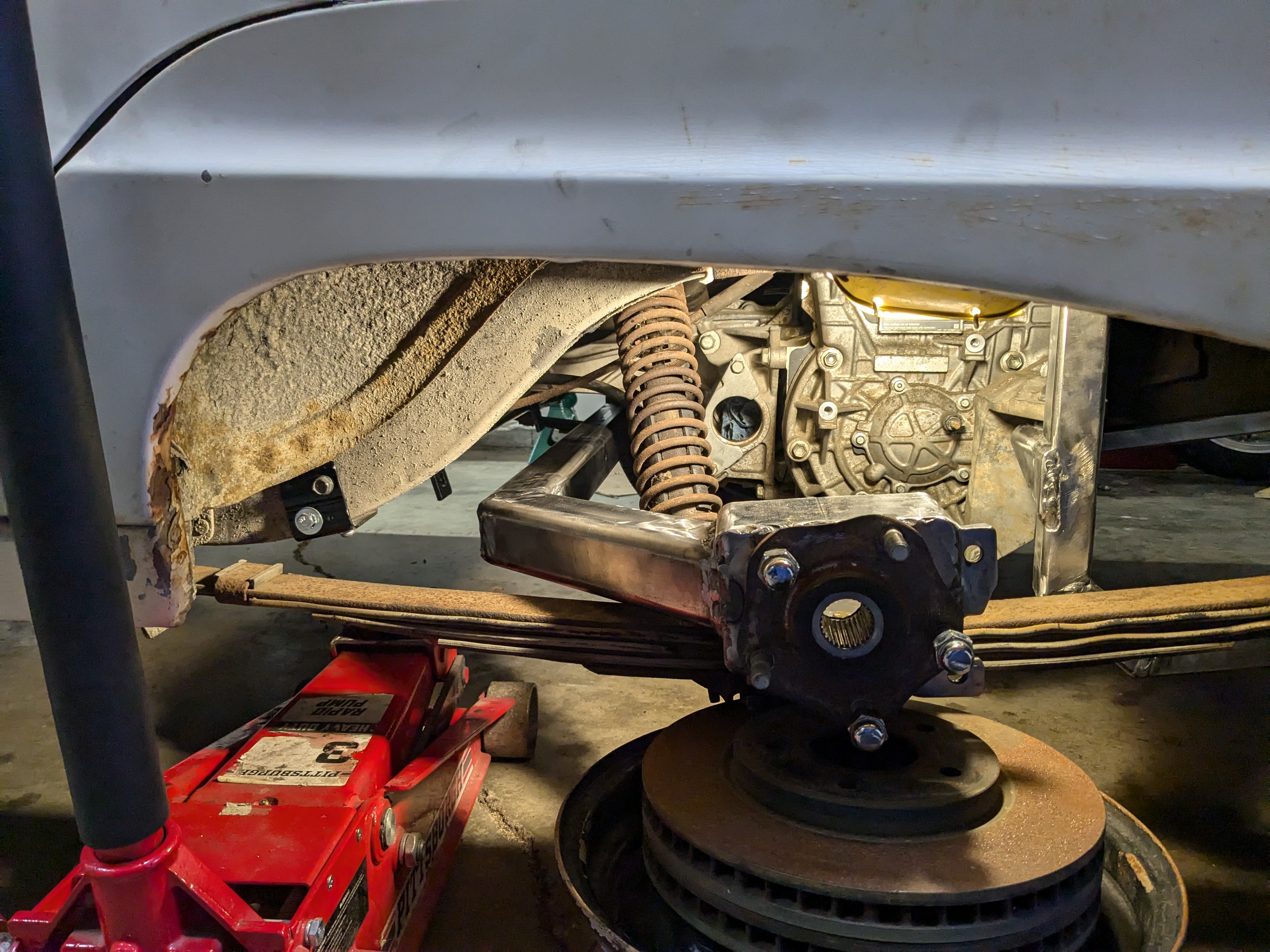
I put the axle in the car, bolted it to the leaf springs (re-using the OEM mounting plates which also attach to the shocks), install the hubs and wheels, and took the car of the jack stands so that all the weight was on the wheels.
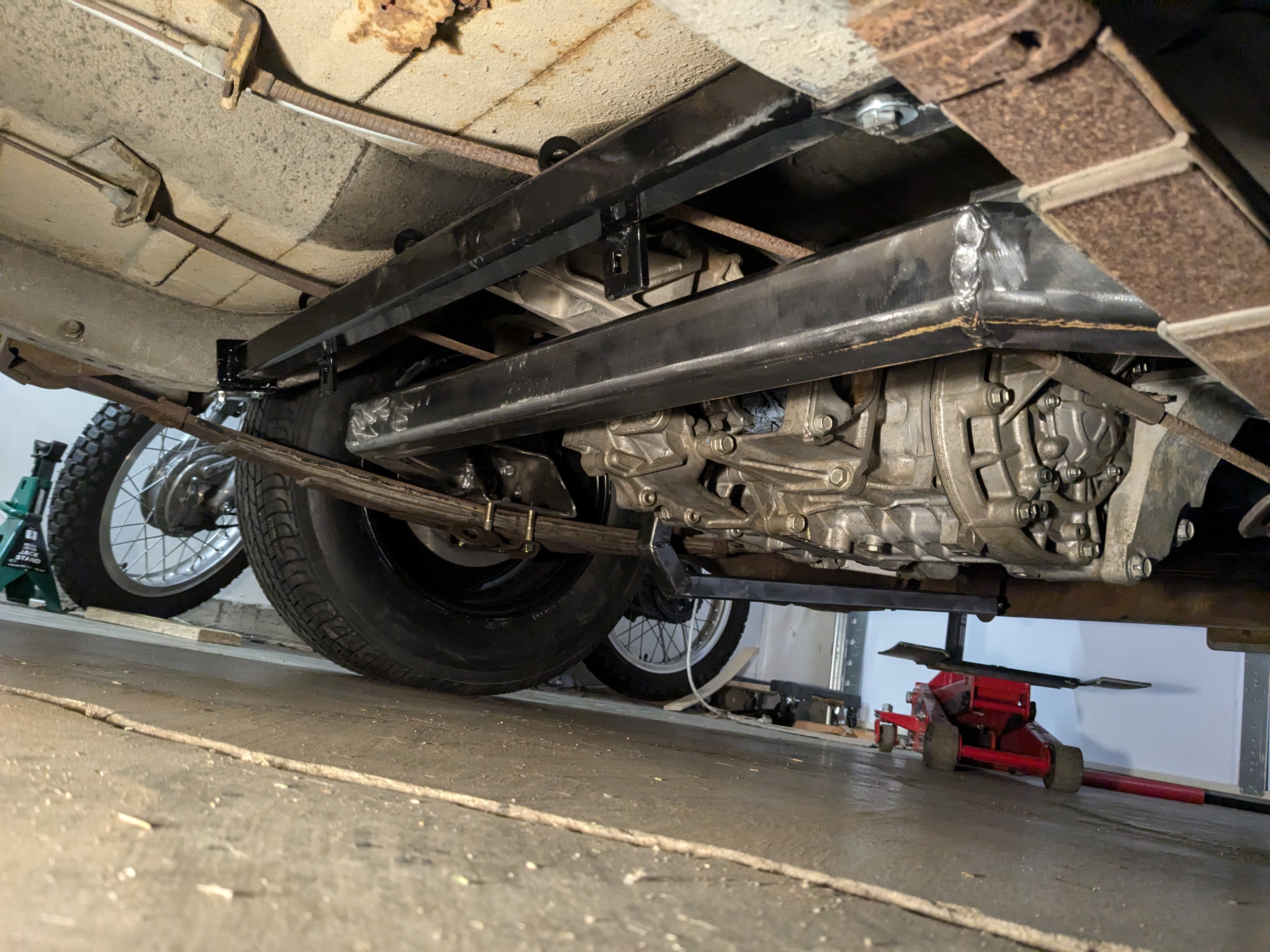
As you can see I have a bit of a problem! It's only about 1.5" from from the front motor mount bracket. I pushed on the back of the car and it made contact very easily.
I installed these aftermarket shock absorbers that came with the car, they stamped "SEARS BOOSTERS" and they give a little extra lift. Not much though, I can compress them with my body weight. But with them, the clearance increased by another inch but it wasn't enough.
So I had to modify the axle tube. This adds about 1.5" of clearance.
But just to be safe, I also created a new front motor mount bracket that adds another inch of clearance.

I have all the clearance I need now!
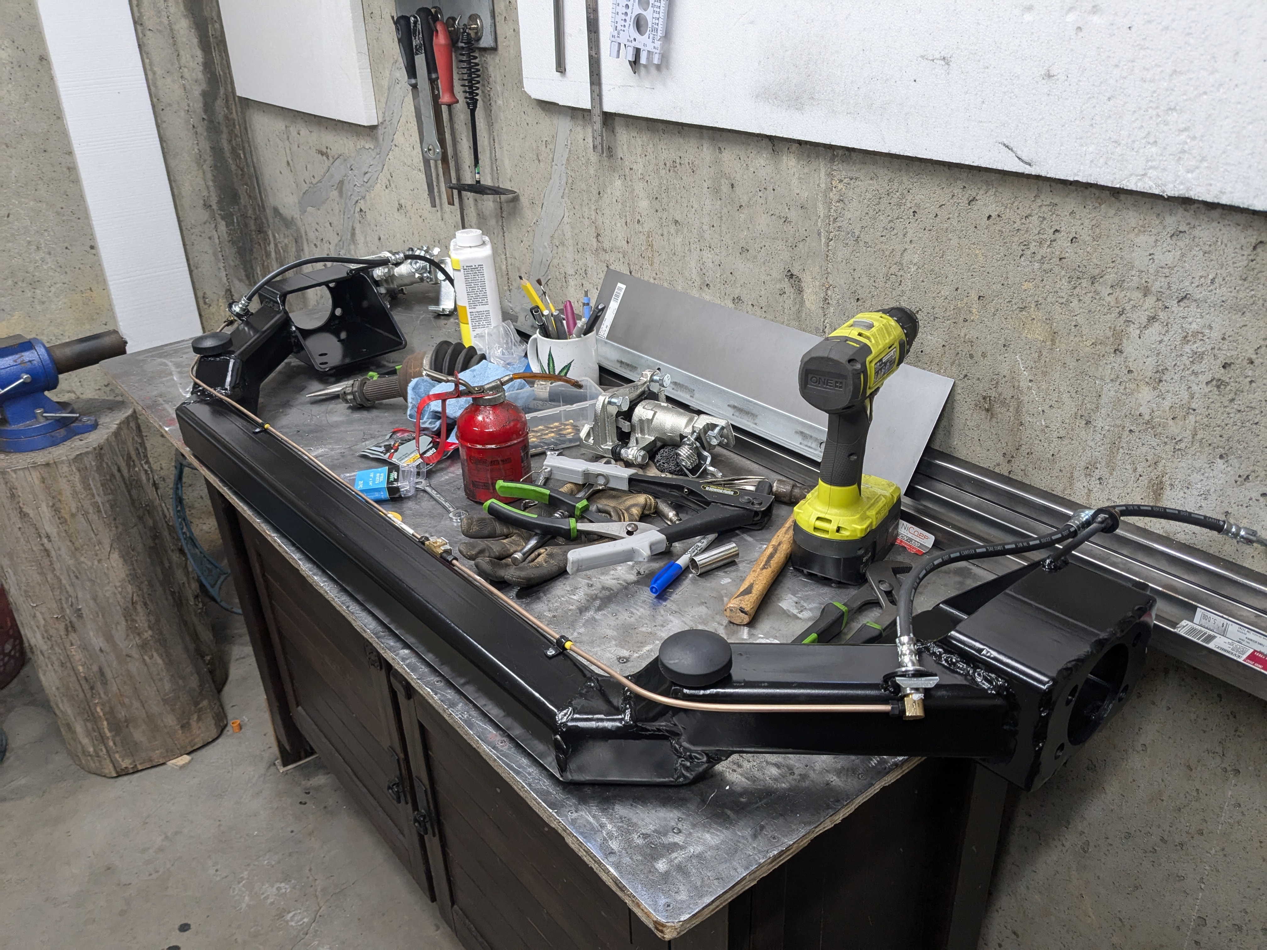
Finally, I could paint it and add the brake hardware and two bump stops.
Oh, and guess what, the De Dion setup also eliminates any potential for axle wrap and wheel hop!
Normal solid axle w/ leaf spring suspensions experience axle wrap with high torque engines - twisting of the leaf springs which causes wheel hop and other problems. It is primarily caused by the interaction of rotational forces between the driveshaft and the pinion gear, and not (as I always assumed until recently) from the wheels and the ground. In other words, if you could suspend a solid axle in space and magically get that yoke and pinion gear to spin clockwise, the axle housing will want to spin counterclockwise to counteract those forces. Newton's laws of motion and all... And note that this has nothing to do with traction with the ground.

Here's where it gets interesting though: a De Dion axle separates the axle tube (or housing) from the axle shafts. You still have torque reactions happening, but now the rotational forces are applied directly to the chassis (in the form of motor mounts, for me) and not to the axle housing/tube. There is nothing to apply torque to the De Dion tube. And of course its the ends of the De Dion tube which are bolted to the leaf springs. So... no more axle wrap! No more wheel hop!
I think I'll make a YouTube video on this concept one day...